
Jun 26, 2026Application Insights
VCSEL Power Ranges by Application: From 3D Sensing to High-Power Arrays
Learn how VCSEL power requirements change with distance, pulse mode, array size, optics, thermal limits, and laser safety.
When engineers discuss VCSEL power, one of the first questions is often, “How many watts does this application need?”
It sounds straightforward, but a single number rarely tells the whole story. A power value may refer to one emitter, a sub-array, or the complete VCSEL array. It may describe continuous-wave output, time-averaged power, pulse peak power, or energy delivered in one pulse.
The same 940 nm VCSEL platform can serve eye tracking, structured light, direct time-of-flight sensing, automotive LiDAR, and industrial heating. Yet the required output can differ by several orders of magnitude.
Even within one application, field of view, working distance, receiver sensitivity, pulse conditions, optics, and thermal design can lead to very different requirements.
This guide explains how to interpret VCSEL power specifications and compares representative power ranges across consumer sensing, automotive systems, data communication, machine vision, precision optics, and high-power arrays.
The ranges below are engineering references, not universal product specifications. Always confirm the measurement plane, operating mode, array size, temperature, drive conditions, and pulse parameters.
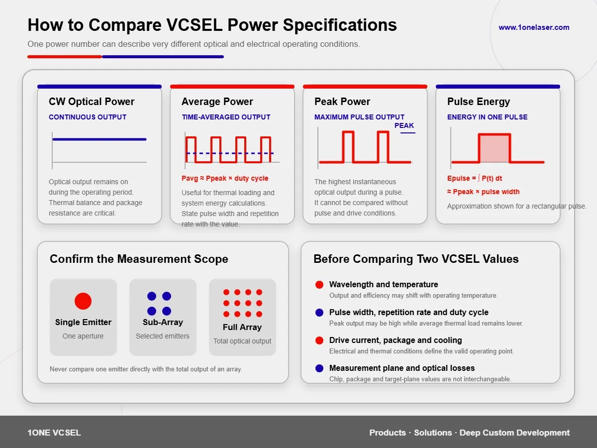
What Does a VCSEL Power Number Actually Mean?
A value such as 100 mW or 10 W is not enough to determine whether a VCSEL is suitable for a project.
Several different measurements may sit behind that number.
Continuous-Wave Optical Power
Continuous-wave, or CW, power describes optical output while the laser remains continuously active.
Because the device generates heat throughout the operating period, sustainable CW output depends heavily on junction temperature, package thermal resistance, cooling area, and ambient temperature.
CW power is important in data links, precision optical sources, continuous illumination, pumping, and industrial energy applications.
Average Optical Power
Average power describes optical energy averaged over time.
For a periodic pulse train, a simplified relationship is:
Average power ≈ Peak power × Duty cycleA source may produce a high pulse peak while maintaining much lower average power and average thermal load because the pulse duration is short.
Pulse Peak Power
Peak power is the highest instantaneous optical output reached during a pulse.
Direct time-of-flight sensing, LiDAR, and selected industrial measurement systems often emphasize peak power because strong, short pulses can improve the returned signal.
A peak-power value should always be accompanied by:
- Pulse width
- Repetition frequency
- Duty cycle
- Peak drive current
- Operating temperature
- Number of active emitters
Comparing two peak-power values without these conditions can be misleading.
Pulse Energy
Pulse energy is the total optical energy contained in one pulse.
Its general relationship is:
Pulse energy = Integral of optical power over the pulse durationFor an approximately rectangular pulse:
Pulse energy ≈ Peak power × Pulse widthIn ranging applications, pulse energy may describe the actual transmitted energy more meaningfully than an isolated peak-power value.
Single-Emitter Power and Total Array Power
The output from one VCSEL aperture cannot be directly compared with the total output of a complete array.
An array may contain tens, hundreds, thousands, or more emitting elements. Its total output also depends on current distribution, emitter uniformity, thermal gradients, and optical coupling efficiency.
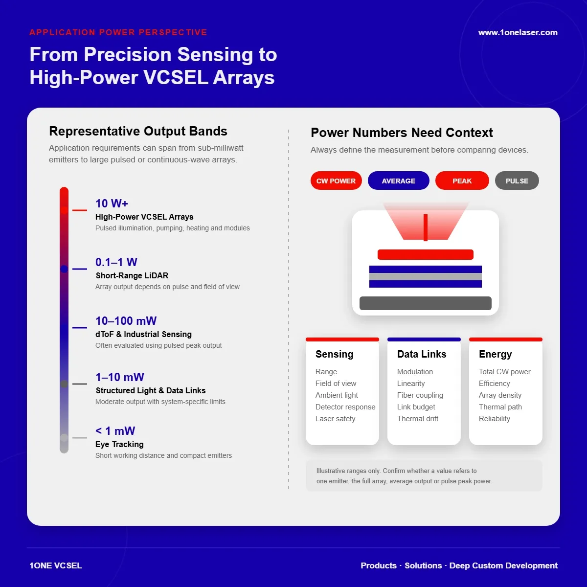
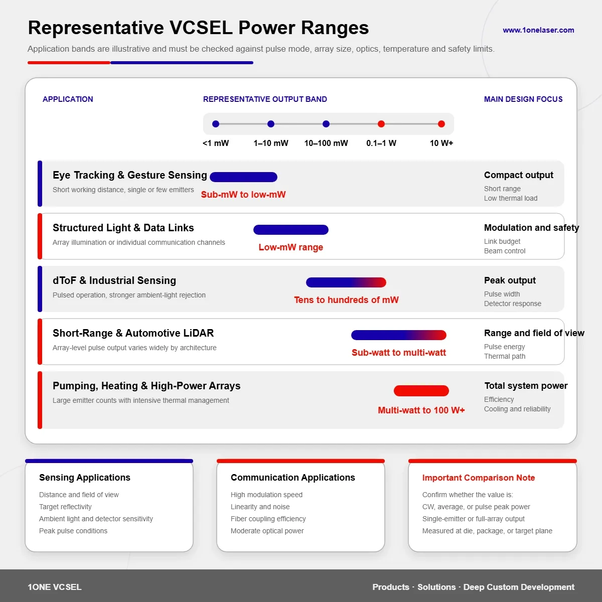
Representative VCSEL Power Ranges by Application
The following values can support early-stage architecture discussions, but they do not replace device data sheets or system testing.
Application | Representative Engineering Range | Common Measurement Basis | Main Design Focus |
|---|---|---|---|
Eye tracking and gesture sensing | Below 1 mW to several mW | Single emitter or compact source | Short range, low heat, laser safety |
Atomic clocks and OPM magnetometers | Sub-mW to several mW | Single-mode CW output | Wavelength stability, linewidth, polarization |
Structured light | Low-mW to tens-of-mW class | Array or module output | Pattern uniformity, DOE efficiency, safety |
High-speed data communication | Approximately 1–10 mW per channel | CW or high-speed modulated output | Bandwidth, linearity, coupling efficiency |
Driver monitoring and cabin sensing | Several mW to tens of mW | Module-level output | Field of view, uniformity, safety |
dToF and industrial sensing | Tens to hundreds of mW class | Pulse peak or array output | Ambient light, pulse conditions, detector response |
Short-range LiDAR | Sub-watt to several-watt class | Array pulse peak output | Range, field of view, thermal design |
Medium- and long-range LiDAR | Several watts to tens of watts or more | Array peak output | Pulse energy, receiver aperture, reliability |
Medical beauty and personal care modules | Low-mW emitters to multi-watt modules | CW, modulated, or total module power | Illuminated area, irradiance, temperature rise |
Optical pumping and industrial heating | Several watts to hundreds of watts or more | Total CW array or module output | Efficiency, cooling, long-term reliability |
These bands can overlap.
A dense structured-light module may produce more total array output than a simple close-range dToF source. At the same time, power measured at the target plane may be substantially lower than output measured at the die or package.
VCSEL Power in Consumer Electronics
Eye Tracking and Gesture Recognition
Eye-tracking systems in AR, VR, and wearable products generally operate across distances of a few centimeters to several tens of centimeters.
They may use one VCSEL, a few emitters, or a compact array. Rather than maximizing total output, the design often prioritizes:
- Low electrical consumption
- Small package size
- Fast modulation
- Stable beam position
- Low temperature rise
- Laser safety
Representative output may fall in the sub-milliwatt to low-milliwatt range, although the final requirement depends on camera sensitivity, optical filters, distance, and beam angle.
3D Structured Light
A structured-light system uses a VCSEL array with a diffractive optical element to project a controlled dot pattern.
The source must deliver enough optical energy for the camera to identify that pattern under the intended distance and ambient-light conditions. At the same time, accessible emission must remain within the safety limits of the finished product.
The original output of the array is only one part of the design. Engineers should also confirm:
- DOE or diffuser transmission efficiency
- Number of projected points
- Power distribution between points
- Working distance
- Receiver signal-to-noise ratio
- Window and lens losses
- Accessible emission in normal and fault conditions
Direct Time-of-Flight Sensing
A direct time-of-flight system calculates distance from the travel time of short optical pulses.
Compared with close-range structured light, dToF often places more emphasis on pulse peak output and receiver sensitivity. Longer range, a wider field of view, or stronger ambient light generally requires more optical link margin.
Explore VCSEL products for sensing and machine vision for time-of-flight, industrial sensing, and machine-vision applications.
Why Automotive VCSEL Power Covers Such a Wide Range
Automotive electronics include both close-range cabin sensing and medium- or long-range exterior detection. As a result, required power can vary widely.
Driver Monitoring and Cabin Sensing
A driver-monitoring system uses near-infrared illumination to observe the driver’s face, eyes, or wider cabin area.
The working distance is relatively short, so module output often remains in the low-milliwatt to tens-of-milliwatt class.
Important considerations include:
- Wide-field illumination
- Reflections from glasses and skin
- Strong daylight conditions
- Camera filtering
- Cabin temperature
- Long operating periods
- Laser safety
Short-Range and Side-View LiDAR
Short-range LiDAR can support parking, blind-zone detection, robotic navigation, and obstacle avoidance.
Array peak output may extend from the sub-watt class into several watts, but the actual requirement depends on illuminated field of view, target reflectivity, receiver aperture, and pulse architecture.
Medium- and Long-Range LiDAR
Longer-range systems need enough returned signal from distant targets. They may therefore use higher peak power, larger VCSEL arrays, or more efficient receiver optics.
Array peak output may reach several watts, tens of watts, or more. Any such value should be qualified by asking:
- Does it describe one emitter or the full array?
- Was it measured at the die, package, or module?
- Is it average output or pulse peak output?
- What pulse width and repetition rate were used?
- What junction temperature and cooling conditions applied?
Why Data Communication Does Not Need Maximum Power
High-speed VCSELs are widely used to transmit modulated optical signals through multimode fiber.
The goal is not to maximize power. It is to maintain sufficient link margin while preserving:
- High modulation bandwidth
- Fast rise and fall times
- Suitable extinction ratio
- Low relative intensity noise
- Stable fiber coupling
- Controlled thermal wavelength drift
- Manageable electrical power and heat
The output of an individual communication channel commonly remains in the low-milliwatt range.
More optical power does not automatically improve the link. It can add thermal load, alter modal behavior, or contribute to receiver saturation.
A communication VCSEL should therefore be selected through a complete link-budget analysis rather than by searching for the largest optical-output number.
Industrial Sensing and Machine Vision
VCSEL requirements in industrial systems can range from a few milliwatts to hundreds of milliwatts or more.
The result depends on:
- Working distance
- Target reflectivity
- Ambient illumination
- Dust and contamination
- Machine vibration
- Window and lens losses
- Detector sensitivity
- Operating duration
A close-range presence sensor may use a low-milliwatt source. A longer-range system operating under bright factory lighting may require stronger pulse output and tighter optical filtering.
Industrial designs should also account for contamination on protective windows. After months of operation, power delivered to the target may be lower than the value measured in a clean laboratory prototype.
Medical Beauty and Personal Care Devices
Power in medical beauty and personal care systems should not be evaluated only at the level of one VCSEL emitter.
These products often illuminate a comparatively large area. An individual emitter may operate in the low-milliwatt range while the complete module reaches several watts or more.
Key design inputs include:
- Wavelength
- Number of emitters
- Illuminated area
- Target-plane irradiance
- Beam uniformity
- CW or pulsed operation
- Skin-side temperature rise
- Exposure duration
- Module cooling
- Finished-product safety assessment
Optical power alone does not establish a medical or health outcome. Any related claim should be supported by complete device validation, regulatory planning, and market-specific compliance.
Atomic Clocks, OPM Magnetometers, and Precision Optics
For atomic clocks, optically pumped magnetometers, and quantum sensing systems, maximum optical power is rarely the first priority.
These projects often focus more heavily on:
- Precise center wavelength
- Single-mode output
- Narrow linewidth
- Wavelength tuning
- Polarization
- Current stability
- Temperature stability
- Long-term drift
The required optical output may remain in the sub-milliwatt to several-milliwatt range, while spectral and modal requirements are far more demanding than those of a general illumination source.
High-Power VCSEL Arrays, Optical Pumping, and Heating
High-power arrays integrate a large number of emitters across a larger die or module.
Total continuous output may reach several watts, tens of watts, hundreds of watts, or more in specialized systems.
Application directions include:
- Solid-state laser pumping
- Industrial heating
- Material processing
- High-power near-infrared illumination
- Thermal treatment
- Scientific optical sources
- Large-area energy delivery
As total output increases, the main challenge shifts from the performance of one aperture to the thermal behavior of the full array and module.
Engineering teams should evaluate:
- Current distribution
- Emitter uniformity
- Electrical-to-optical efficiency
- Die and submount thermal resistance
- Bonding voids
- Cooling architecture
- Thermal cycling
- Optical-window durability
- Long-term power degradation
High power is not achieved by emitter count alone. Uneven current or cooling can create local hot spots that limit the reliability of the entire array.
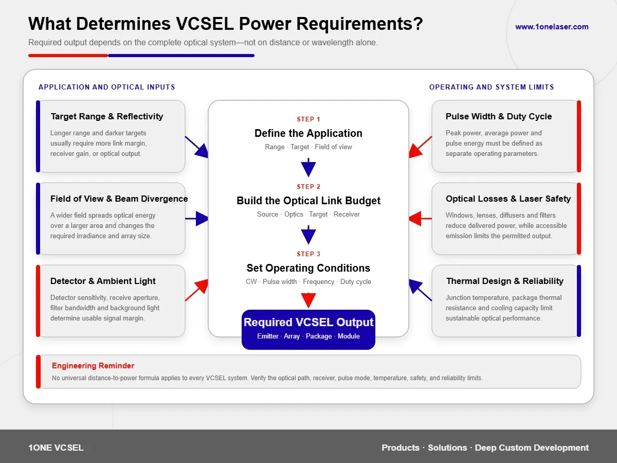
Why Distance Alone Does Not Define Required Power
A common simplification is that doubling distance always requires four times the power, or that power must increase exponentially with range.
Real systems are more complicated.
Required transmitter output depends on the complete optical link, including:
- Beam divergence
- Illumination field of view
- Target reflectivity
- Target size and angle
- Transmitter optical efficiency
- Receiver-lens aperture
- Detector quantum efficiency
- Receiver bandwidth
- Ambient-light noise
- Pulse integration time
- Algorithmic processing gain
A narrow-field system and a wide-field system operating at the same distance can require very different transmitter power.
Increasing receiver aperture, improving optical filtering, using a more sensitive detector, or optimizing the signal-processing algorithm may produce better results than simply increasing VCSEL output.
Laser Safety Is a System-Level Constraint
A VCSEL die should not automatically be described as eye-safe.
The safety classification of the finished product depends on:
- Wavelength
- CW or pulsed operation
- Pulse duration
- Repetition frequency
- Exposure time
- Beam diameter
- Beam divergence
- Diffusers and diffractive optical elements
- Optical fault conditions
- User-accessible locations
The same VCSEL can produce different safety results when installed in different optical architectures.
Products used near people, including consumer electronics, cabin sensing, personal care devices, and medical beauty systems, should undergo system-level assessment under the applicable edition of IEC 60825-1 or the relevant target-market requirements.
How Thermal Design Limits Real Output
VCSEL output, efficiency, and wavelength all respond to junction temperature.
Higher temperature may lead to:
- Reduced optical output
- Center-wavelength drift
- Changes in threshold current
- Lower efficiency
- Emitter non-uniformity
- Changes in beam or modal behavior
- Shorter operating life
A pulsed system may have lower average power, but high peak current can still create transient heating, current crowding, and local stress.
VCSEL selection should therefore include the package and complete thermal path, rather than relying only on maximum power measured at room temperature under short laboratory pulses.
How to Specify VCSEL Power to a Supplier
A useful inquiry should contain more than “We need a 10 W VCSEL.”
Include the following information whenever possible.
Optical Requirements
- Center wavelength and tolerance
- Average power, peak power, or pulse energy
- Single-emitter output or total array output
- Beam divergence
- Working distance
- Field of view
- Target-plane spot size or irradiance
Electrical Requirements
- CW, modulated, or pulsed operation
- Drive current
- Pulse width
- Repetition frequency
- Duty cycle
- Available drive voltage
Thermal and Mechanical Requirements
- Ambient-temperature range
- Maximum operating duration
- Cooling method
- Package-size limits
- Bare die, submount, SMD package, or complete module
- Available thermal space
Project Information
- Laboratory evaluation, prototype, or production stage
- Sample quantity
- Expected production quantity
- Target market
- Safety and regulatory requirements
Early-stage teams can use Request VCSEL Samples for Early Evaluation to submit a sample requirement.
When Is a Custom Array, Package, or Power Level Needed?
Customization becomes relevant when:
- Standard products cannot provide enough output
- A special emitter count or pattern is required
- Pulse peak output must be optimized
- Package thermal resistance must be reduced
- Module space is limited
- A specific divergence or illumination area is required
- Multiple wavelengths must be integrated
- Bare die or custom bond-pad access is needed
- Project-specific testing is required
- The program must move from samples into long-term OEM production
Customization does not always mean redesigning the complete wafer structure.
Many projects can be improved through array layout, submount design, packaging, drive conditions, diffusers, lenses, and thermal architecture.
For high-power arrays, special packages, or complete optical-module development, submit the project through Custom Development & ODM.
Frequently Asked Questions
Is VCSEL power normally specified in milliwatts or watts?
Single emitters and lower-power devices are commonly specified in milliwatts. Large arrays, high-power modules, pumping sources, and heating systems are usually specified in watts. Confirm whether the value applies to one emitter or the full array.
What is the difference between peak power and average power?
Peak power is the highest instantaneous output during a pulse. Average power is the output averaged over time and depends on pulse width, repetition frequency, and duty cycle.
Can the same 940 nm VCSEL be used for structured light and LiDAR?
The wavelength may be the same, but the devices are not necessarily interchangeable. Structured-light and LiDAR systems can require different array layouts, pulse conditions, peak power, beam properties, packaging, and cooling.
Does a longer detection range always require more VCSEL power?
It normally requires more optical link margin, but higher transmitter power is not the only option. Receiver aperture, detector sensitivity, filters, field of view, and signal processing also influence maximum range.
Does high pulse peak power always create high thermal load?
Not necessarily. Average thermal load depends on pulse width, repetition rate, and duty cycle. However, high peak current can still create transient heating, current crowding, and reliability concerns.
Can a VCSEL be selected from maximum power alone?
No. Wavelength, operating mode, beam behavior, temperature, package, receiver, laser safety, and long-term reliability should also be evaluated.
Further Reading, Standards, and Technical References
- IEC 60825-1: Safety of Laser Products, Equipment Classification and Requirements A major international reference for laser classification, measurement conditions, labeling, and manufacturer requirements. Confirm the applicable edition and regional adoption.
- FDA: Laser Products and Instruments An official U.S. resource covering laser products, manufacturer responsibilities, and radiation-emitting product requirements.
- RP Photonics Encyclopedia: Vertical-Cavity Surface-Emitting Lasers A technical overview of VCSEL structure, operating principles, arrays, beam behavior, and applications.
- K. Iga: Surface-Emitting Laser—Its Birth and Generation of New Optoelectronics Field A review of the development of surface-emitting lasers and their role in optoelectronics.
- NIST Time and Frequency Division Research resources related to atomic clocks, frequency standards, precision timing, and measurement science.
Standards and regulatory links are starting points for research. They do not replace project-specific testing, product classification, risk assessment, or professional compliance review.
From a Power Number to a Complete Optical System
VCSEL power ranges can extend from below one milliwatt to hundreds of watts, but higher output does not automatically produce a better system.
Sensing applications must balance transmission, reception, ambient light, and laser safety. Communication systems prioritize modulation and link quality. Energy applications focus on total CW output, efficiency, and thermal management.
A practical selection process begins by defining:
- What wavelength is required?
- What is the working distance?
- Is the source CW or pulsed?
- Does the value describe peak power, average power, or pulse energy?
- Is it measured for one emitter or the complete array?
- How much power will be lost through the optics?
- How much return signal does the receiver need?
- What temperature and safety limits apply?
Once these conditions are clear, the engineering team can determine whether a standard VCSEL is sufficient or whether the array, package, driver, or complete optical module should be customized.