
808nm
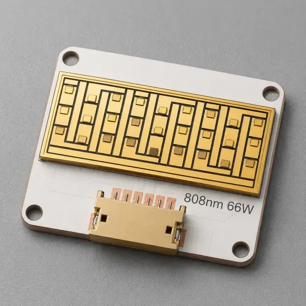
808nm 66W VCSEL COB Module
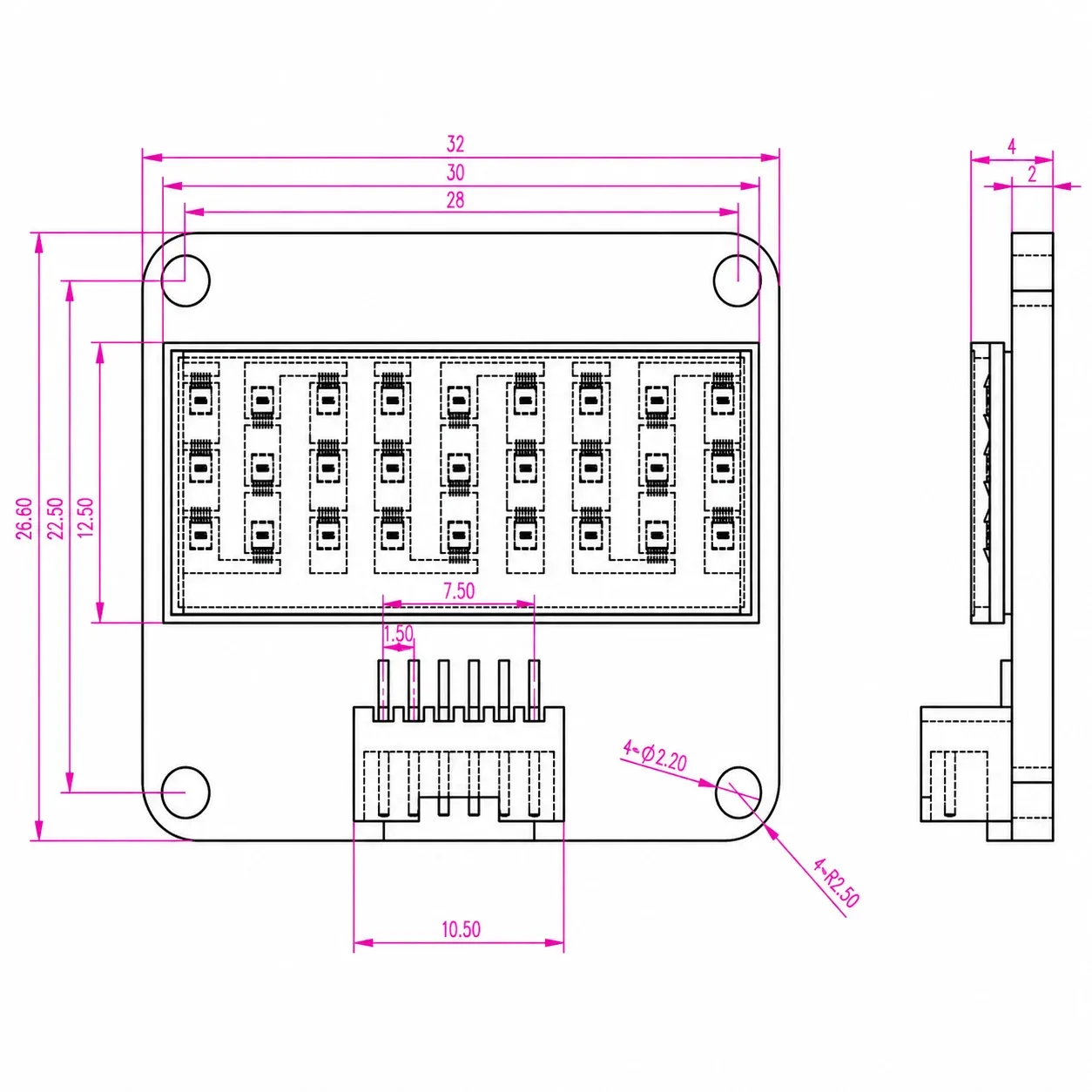
808nm 66W VCSEL COB module with a 2.8 × 1.0 cm homogenized spot for QCW hair removal equipment light-source development and high-power NIR integration.
Specifications
- Package Type
- COB Encapsulation
- Wavelength
- 808nm typ. (798nm – 818nm)
- Optical Output Power
- 66 W typ. at IF = 10.5 A
- Threshold Current
- 1830 mA typ.
- Forward Voltage
- 20.5 V typ. at IF = 10.5 A
- Operating Condition
- QCW, 5 ms pulse length, 1% duty cycle, 25 °C
- Spot / Beam
- 2.8 cm × 1.0 cm, spatially homogenized beam profile
1. 808nm 66W VCSEL COB Module for High-Power Light-Source Integration
The 808nm 66W VCSEL COB module is developed for component-level high-power light-source integration. It provides 66W typical optical output at a forward current of 10.5A under the specified QCW operating condition and produces a spatially homogenized 2.8 × 1.0 cm spot.
The COB-encapsulated configuration provides an integration path for equipment developers that require a prepared optical source rather than unpackaged VCSEL bare die. For broader thermal, optical and module-level engineering support, review our High-Power NIR & Optical Modules solution.
Lead Time: In-stock products are dispatched within 3 business days; custom-packaged products have a lead time of 15–20 days.
MOQ: The minimum order quantity is 1 reel; selected special models support small-batch orders.
2. Optical Configuration and COB Module Design
The following parameters are based on the product datasheet. Electrical and optical values must be evaluated under the specified test conditions rather than interpreted as unconditional finished-system performance.
Parameter | Specified Value |
|---|---|
Package Type | COB Encapsulation |
Peak Wavelength | 808 nm typ.; 798nm – 818nm range |
Optical Output Power | 66 W typ. at IF = 10.5 A |
Threshold Current | 1830 mA typ. |
Forward Voltage | 20.5 V typ. at IF = 10.5 A |
Operating Condition | 25 °C, QCW mode, 5 ms pulse length and 1% duty cycle |
Spot Size | 2.8 cm × 1.0 cm |
Beam Profile | Spatially homogenized beam profile |
Customization | Available for project-specific evaluation |
3. Thermal, Optical and Downstream Equipment Integration
Electrical and Thermal Integration
The 66W optical output and 20.5V typical forward voltage are specified at IF = 10.5A under a 5 ms pulse length, 1% duty cycle and 25 °C test condition. Driver design, pulse control, heat transfer, mounting pressure and temperature monitoring must therefore be validated together at the module and equipment level.
The published values should not be extrapolated directly to other duty cycles, pulse widths or thermal conditions. Equipment developers should confirm electrical margins, thermal interfaces and operating limits using the actual mechanical assembly and control system.
Homogenized Beam and Optical Window
The module is specified with a 2.8 × 1.0 cm spot and a spatially homogenized beam profile. The final irradiated area and optical distribution can still be affected by working distance, downstream windows, optical interfaces, module alignment and equipment enclosure design.
The datasheet provides directional far-field distribution curves for engineering evaluation instead of a single universal divergence value. Optical validation should therefore use the complete module, downstream optical path and intended working geometry.
Hair Removal Equipment Light-Source Development
The datasheet identifies hair removal equipment light-source development as an intended component-level direction. The module serves as a high-power NIR optical source within an equipment architecture that includes electrical driving, thermal management, mechanical mounting, optical delivery and safety controls.
This application description does not represent finished-device medical efficacy, clinical performance, safety approval or regulatory clearance. The finished-device manufacturer remains responsible for optical safety, thermal safety, exposure control, system testing and applicable regulatory compliance.
Related Articles
4. Evaluation Kit and Documentation Support
Evaluation samples are available for electrical, thermal, optical and beam-profile assessment under project-specific operating conditions. Testing should reproduce the intended driver, cooling structure, optical path and equipment-level mounting environment. An Evaluation Kit with 10 pcs / KIT is available for electrical, thermal, optical and beam-profile evaluation under the selected operating conditions.
Samples & Pilot Production: Evaluation kits, low-volume pilot production, and pre-production validation are supported.
For component-level project evaluation, an Initial Product Report covering the Laser Diode Series and VCSEL Laser Diode Chip Series has been filed with the U.S. FDA CDRH. This filing supports technical documentation and product evaluation.
For applicable products, CE, EMC, EN 60825, LVD, RoHS, REACH and halogen-free certification and compliance documents are available. Documentation depends on the corresponding product model and does not represent certification of the customer's finished device.
5. Frequently Asked Questions
FAQ 1. What operating conditions are specified for the 808nm 66W VCSEL COB module?
The module is specified at 25 °C in QCW mode using a 5 ms pulse length and 1% duty cycle. Under the stated test condition, it provides 66W typical optical output at IF = 10.5A, with a typical forward voltage of 20.5V. Operation outside these conditions requires separate electrical, optical and thermal validation.
FAQ 2. How does the 808nm 66W VCSEL COB module differ from the 808nm 60W VCSEL bare die?
The COB module is an encapsulated light-source assembly with a specified homogenized spot, while the 808nm 60W High-Power VCSEL Bare Die is intended for customers developing their own die attach, wire bonding, thermal interface, optical packaging and module structure. Selection depends on whether the project requires chip-level packaging freedom or a prepared COB optical-source format.
FAQ 3. Can the 808nm 66W VCSEL COB module be used for hair removal equipment development?
The datasheet identifies hair removal equipment light-source development as an intended component-level direction. Suitability for a finished system depends on the customer's driver, cooling, optical delivery, exposure controls, enclosure, safety design and regulatory validation. The component specification does not establish treatment efficacy or finished-device approval.