
Sep 26, 2026Technical Insights
How Do You Specify Linewidth and SMSR for a VCSEL
Learn how to specify VCSEL linewidth, SMSR and polarization requirements for atomic clocks, magnetometers and precision sensors, including test conditions and RFQ wording.
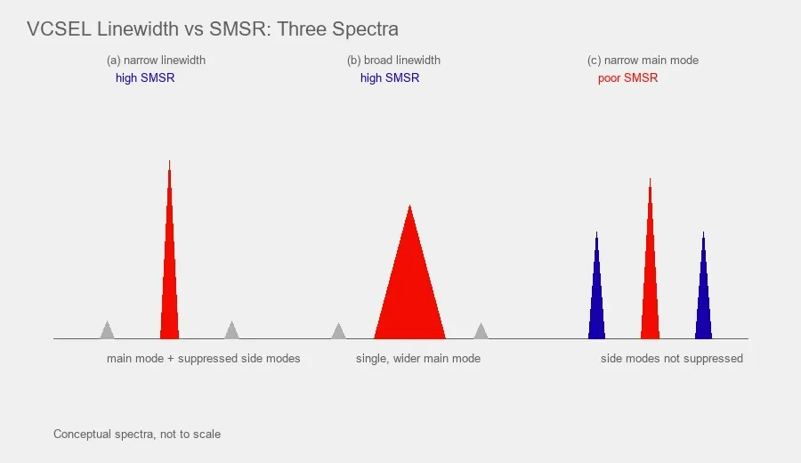
If a precision sensing project needs a single mode VCSEL, writing “single mode VCSEL with narrow linewidth” in the RFQ is not enough.
The supplier still does not know how narrow the linewidth must be, how much side mode suppression is acceptable, whether polarization stability matters, or under which current and temperature those values must hold.
For atomic clocks, optically pumped magnetometers, vapor cell sensors and other spectroscopy based systems, at least three spectral and polarization parameters should normally be separated:
- Spectral linewidth
- Side mode suppression ratio or SMSR
- Polarization extinction ratio or another clearly defined polarization metric
These parameters describe different failure modes. A VCSEL can have good SMSR but an unsuitable linewidth. It can have a narrow main mode but unstable polarization. It can meet all three values at one laboratory operating point and fail after the current or temperature moves.
The correct specification is therefore not one number. It is a set of numbers tied to the actual operating condition of the system.
Two further parameters belong in the same specification whenever the VCSEL is not a simple free running CW source. The classic list of VCSEL requirements for CPT atomic clocks, established in early chip scale atomic clock work, is single mode operation, single polarization operation, modulation bandwidth above roughly 4GHz, low power consumption, narrow linewidth and low relative intensity noise or RIN. Linewidth, SMSR and polarization are the spectral core, but for a modulated clock source the modulation bandwidth and the RIN can be just as decisive, and they are covered in their own sections below. Treat the spectral parameters as the foundation and add modulation and RIN when the architecture demands them.
Start by defining what the atomic or sensing system needs
A component specification should begin with the physical interaction the VCSEL must support.
For a rubidium D1 vapor cell system, the project may need a source near 795nm. A cesium D1 system may require a source near 894.6nm. A clock may also require direct modulation, while an OPM may place stronger emphasis on polarization stability, low magnetic packaging or optical power through a specific vapor cell.
The source requirement should therefore begin with the application architecture.
A useful first page of a VCSEL requirement might include:
Requirement | Example information |
|---|---|
Application | Rb atomic clock, Rb OPM, Cs OPM or precision absorption sensor |
Target transition | Rb D1, Cs D1 or another defined line |
Nominal wavelength | 795nm, 894.6nm or project specific |
Operating temperature | Laser die or package temperature range |
Operating current | Nominal current and permitted range |
Operating mode | CW, pulsed or RF modulated |
Optical power | Required range at the source or after optics |
Linewidth | Maximum value under defined conditions |
SMSR | Minimum value under defined conditions |
Polarization | PER, OPSR or polarization stability requirement |
Tuning | Current tuning and temperature tuning range |
Package | Bare die, TO package, nonmagnetic package or custom module |
Once these conditions are clear, linewidth and SMSR become meaningful engineering specifications rather than marketing descriptions.
Linewidth tells you how spectrally concentrated the main laser mode is
Laser linewidth describes the frequency width of the emitted optical line.
Laser linewidth is usually expressed as an effective full width at half maximum in MHz, but the reported value depends on the measurement method, observation bandwidth and noise timescale.
A narrower linewidth means that the optical energy is concentrated into a narrower frequency interval. That matters when the laser interacts with a narrow atomic or molecular resonance, because excessive laser frequency noise or spectral width can broaden the observed signal, reduce contrast, convert frequency fluctuations into amplitude noise, or limit the stability of the final sensing system.
This is especially important in atomic clocks.
Recent work comparing a conventional VCSEL source with a much narrower chip external cavity diode laser in a compact rubidium CPT clock showed that the broader VCSEL linewidth can contribute to FM to AM noise and clock instability. The same work also demonstrates why there is no universal linewidth number for every clock. A very compact VCSEL based architecture can accept a broader source because size, power consumption and GHz modulation capability are also critical design constraints.
It also helps to know where standard devices sit. Because a VCSEL has a very short cavity and high round trip loss, a conventional device commonly emits with a linewidth above 100MHz, which is why atomic grade parts are engineered specifically to narrow it. A 2026 monolithically integrated passive cavity VCSEL at the cesium D1 line of 894.6nm reported an intrinsic linewidth compressed to roughly 1MHz with SMSR above 35dB and orthogonal polarization suppression above 25dB, without external optical feedback. Published atomic-sensing VCSEL examples often fall in the tens-of-MHz range. This spread, from above 100MHz down to about 1MHz, is exactly why a linewidth requirement only means something once it is attached to a device class and an operating point rather than written as a single global target.
The practical engineering question is therefore not:
What is the narrowest VCSEL available
It is:
What maximum linewidth can this atomic or sensing architecture tolerate while still meeting its system level signal and stability target
Do not specify linewidth without a measurement definition
One of the most common procurement mistakes is writing only:
Linewidth ≤ 50MHz
That looks precise, but several questions remain unanswered.
Was the value measured as optical spectrum FWHM?
Was it measured by heterodyne or delayed self heterodyne?
What observation time or frequency noise range is included?
Was the device free running or frequency locked?
Was it measured before or after RF modulation?
What were the laser current and temperature?
Was the laser mounted as bare die, on a submount or in its final package?
For relatively broad VCSEL linewidths, the supplier may use a spectroscopy based method, heterodyne method or another qualified technique. For much narrower lasers, linewidth measurement itself becomes a measurement science problem because frequency noise at different time scales changes the reported result.
This is why the RFQ should define the measurement interpretation whenever linewidth is a critical acceptance parameter.
A practical requirement could read:
Spectral linewidth shall be ≤30MHz at the defined operating current and laser temperature in CW operation. Supplier shall state the measurement method and linewidth definition used for acceptance testing.
This wording is much stronger than simply asking for a “30MHz laser.”
If the customer has a preferred measurement method, resolution bandwidth or fit model, that should be added as well.
A linewidth number must be tied to current and temperature
VCSELs are semiconductor lasers. Their optical behavior changes with drive current and junction temperature.
That means a laser that shows acceptable linewidth at one point may not show identical behavior across the complete operating envelope.
For precision optical sources, request linewidth data at one of three levels depending on the project.
Level 1
One defined operating point.
Example:
- Laser/package temperature = 70 °C, measured at the defined control point
- IF = 2mA
- CW
- linewidth ≤30MHz
Throughout this article, laser temperature refers to this defined control point, not the junction temperature, since package, thermistor and junction temperature are not identical. This may be enough for an early evaluation when the system will operate close to a fixed setpoint.
Level 2
A defined operating window.
Example:
- laser temperature from 65 °C to 75 °C
- current from 1.8mA to 2.2mA
- linewidth ≤40MHz throughout the window
This is more useful for a product that must absorb manufacturing and temperature control tolerances.
Level 3
A characterization map.
For demanding R&D or production qualification, request measured linewidth versus current and temperature together with mode and polarization behavior.
This can reveal an important issue that a single datasheet point hides. The source may remain spectrally clean in the center of the operating region but approach a mode transition or polarization switching boundary near one edge
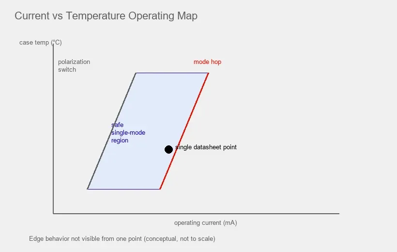
.SMSR answers a different question
SMSR means side mode suppression ratio.
It compares the optical power of the dominant lasing mode with the strongest unwanted side mode and is normally expressed in dB.
A higher SMSR means the main mode dominates the optical spectrum more strongly.
This is useful when an atomic or precision sensing system requires most of the optical power to remain in one selected spectral mode.
However, SMSR does not tell you how narrow that main mode is.
Consider two sources.
Source A has a strong single main peak and weak side modes, so the SMSR is high. The main peak itself may still have a relatively broad linewidth.
Source B has a very narrow main peak but also a second unwanted mode only slightly weaker than the main peak, producing poor SMSR.
Neither parameter replaces the other.
This is why the statement “single mode, SMSR ≥30dB” is not equivalent to “narrow linewidth.”
What SMSR means for an atomic or precision sensor
Unwanted optical modes can interact with the sensing medium differently from the intended mode.
In a vapor cell system, a side mode may fall at a different detuning from the atomic transition. Depending on the application, that can affect optical pumping efficiency, absorption background, signal contrast or the stability of a detected resonance.
For that reason, atomic sensing VCSELs are often specified with SMSR values around 20dB, 30dB, 35dB or higher depending on the design.
These numbers are examples from real devices and published research, not universal pass and fail thresholds.
A recent review of chip scale hot atomic devices reports VCSEL designs with SMSR values above 30dB and 35dB in different atomic clock and sensing developments. Published and commercial parts show the same range in practice. One commercial single mode 894nm VCSEL developed for quantum applications was reported at roughly 30MHz linewidth with SMSR near 28dB, while a research 795nm single mode device for rubidium quantum sensing reported about 6.8mW output at 49.8MHz linewidth with SMSR above 40dB held across 25 °C to 85 °C. Current 1ONELASER Rb OPM and Cs OPM source pages likewise use application specific single mode specifications rather than one generic number for every wavelength. The point is not to copy any of these figures but to notice that credible sources disagree by tens of dB and tens of MHz because they were optimised for different systems.
The engineering rule is simple:
Specify the minimum SMSR required by the optical system, and define where in the operating range it must be maintained.
SMSR also needs test conditions
An SMSR value can change with drive current, temperature, mounting stress and optical feedback.
A supplier should therefore know whether the requirement applies only at the nominal operating point or across a full range.
Instead of writing:
SMSR ≥35dB
write:
SMSR shall be ≥35dB at IF = 2.0mA, laser temperature = 70 °C, CW operation, measured after thermal stabilization.
Or for a wider requirement:
SMSR shall remain ≥30dB over IF = 1.8mA to 2.2mA and laser temperature = 65 °C to 75 °C.
For a bare die project, also decide whether acceptance testing applies before die attach, after customer assembly or to a supplier assembled submount.
Packaging stress can influence VCSEL mode and polarization behavior, so this detail matters when the final device is sensitive to small optical changes.
Polarization is a third independent specification
Many atomic sensing systems do not use an arbitrary polarization state.
Optical pumping frequently relies on a defined linear polarization followed by a quarter wave plate or another optical element to create a controlled circular polarization state at the vapor cell.
The VCSEL therefore needs repeatable polarization behavior.
A common specification is polarization extinction ratio or PER. Some literature and devices instead use orthogonal polarization suppression ratio or OPSR.
Although the exact naming and measurement setup can differ, the purpose is similar: quantify how strongly the desired polarization dominates the orthogonal component.
For procurement, do not assume that “single mode” automatically means “single polarization.”
These are separate characteristics.
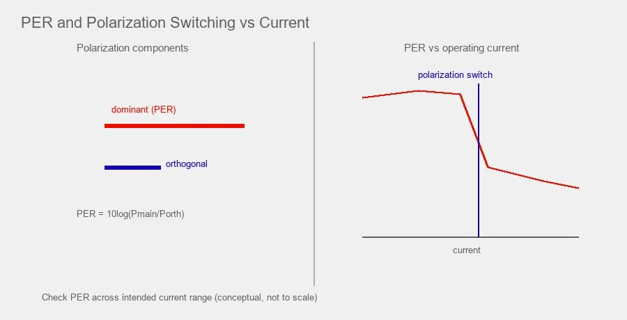
VCSELs can also exhibit polarization switching as current, temperature, feedback or mechanical stress changes. A device can therefore meet a PER target at one point but rotate or switch polarization elsewhere in the operating range.
For an OPM or clock, this can matter even if wavelength and SMSR remain acceptable.
Specify polarization in terms the supplier can test
A good polarization requirement should answer four questions.
What metric is required
For example:
- PER ≥20dB
- OPSR ≥25dB
At what current and temperature
For example:
- IF = 2mA
- laser temperature = 70 °C
What polarization orientation matters
Some systems only need one stable linear axis.
Others need the polarization axis to fall within a defined angular tolerance relative to the die or package.
Must the polarization remain stable across a range
If the device current is modulated or temperature varies, specify whether polarization switching is allowed.
A stronger RFQ statement might read:
PER shall be ≥20dB at the nominal operating point. No polarization switching shall occur over IF = 1.8mA to 2.2mA and laser temperature = 65 °C to 75 °C. Supplier shall identify the dominant polarization axis relative to the package or die reference where available.
That sentence contains much more usable information than “polarization stable VCSEL.
Linewidth SMSR and PER should be specified together
For a precision VCSEL, a useful spectral requirement should usually be written as one block.
For example:
Parameter | Project requirement | Test condition |
|---|---|---|
Peak wavelength | 795nm within agreed tolerance | 70 °C, 2mA, CW |
Spectral linewidth | ≤30MHz | Same operating point |
SMSR | ≥35dB | Same operating point |
PER | ≥20dB | Same operating point |
Mode stability | No mode hop in operating window | 65 °C to 75 °C, 1.8mA to 2.2mA |
Polarization stability | No polarization switching | Same window |
Optical power | Project defined range | Same operating point |
RIN | Project defined maximum, if noise sensitive | Same operating point and frequency band |
Modulation bandwidth | Project defined minimum, if directly modulated | At nominal bias, e.g. GHz range for CPT |
The last two rows only apply to noise sensitive or directly modulated systems, but when they apply they are not optional extras. Leaving RIN or modulation response undefined for a CPT clock is as risky as leaving linewidth undefined.
Using the same test point matters.
If wavelength is measured at 70 °C, SMSR at 25 °C and linewidth under a different current, the datasheet can contain individually good numbers that never occur at the same time in the actual system.
Why a standard datasheet value is not always the final project specification
A standard product datasheet describes the normal production specification of that product.
It is not automatically the tightest performance every individual die can achieve.
Manufacturing distributions exist. Within one production population, some devices may have a tighter wavelength position, narrower linewidth, higher SMSR or stronger PER than the standard guaranteed limit.
This creates an opportunity for project specific screening or binning.
For example, a standard device may be published as:
- Linewidth ≤50MHz
- SMSR ≥30dB
- PER ≥20dB
A project might ask whether a subset can be screened for:
- Linewidth ≤35MHz
- SMSR ≥35dB
- PER ≥20dB
Whether this is practical depends on actual production distribution, test capability, quantity, yield and operating condition.
A supplier cannot manufacture any requested combination simply by changing the label. Tighter screening usually reduces yield and can affect price and lead time.
The correct request is therefore:
Please evaluate whether project specific screening is available for the following spectral limits under the stated operating conditions. Please advise achievable yield, sample quantity, test method and whether these limits can be guaranteed for production.
That wording treats customization as an engineering screening question rather than assuming an arbitrary tighter specification is available.
Custom wavelength binning and custom spectral screening are not the same thing
It is useful to separate two ideas.
Wavelength binning
The supplier sorts devices by center wavelength at an agreed current and temperature.
This is useful when the system needs the laser to reach an atomic line with a specific temperature tuning margin.
Spectral screening
The supplier selects devices according to linewidth, SMSR, PER or other optical characteristics.
The two can be combined, but every additional limit reduces the pool of devices that qualify.
A procurement team should therefore identify which requirements are true system limits and which are preferences.
If the clock can tolerate 50MHz but the engineer writes 20MHz because “smaller is better,” the project may create unnecessary cost and supply risk without improving the final instrument.
Do not forget modulation when the laser will not operate as a simple CW source
This point is especially important for CPT atomic clocks.
A VCSEL may be directly modulated at GHz frequencies to create optical sidebands.
Once the device is modulated, the optical spectrum no longer looks like the free running CW spectrum.
The clock may care about:
- Carrier power
- First order sideband power
- Sideband symmetry
- Modulation index
- Residual amplitude modulation
- Phase noise
- Bias current
- RF drive power
- Modulation response versus temperature
A linewidth and SMSR requirement measured only in unmodulated CW operation is still useful for component characterization, but it does not replace modulation testing.
For a modulated system, specify both conditions separately.
Example:
CW spectral acceptance: linewidth ≤30MHz, SMSR ≥35dB at 70 °C and 2mA.
System modulation evaluation: characterize optical sideband spectrum at the project RF frequency and nominal bias current.
This keeps the source specification technically honest.
How to write a RIN requirement
When the system is noise sensitive, relative intensity noise deserves the same discipline as linewidth. A RIN limit is only testable if it states the RIN spectral-density convention and units, commonly dBc/Hz, together with the relevant offset-frequency range, the bias current and the laser temperature. For atomic clocks and magnetometers, define the offset-frequency range relevant to the photodetector, demodulation and servo chain. The GHz modulation frequency should be specified separately as a modulation-response requirement rather than assumed to be the relevant RIN measurement band. If the system integrates noise over a band rather than caring about a single frequency, ask for an integrated RIN figure over the defined bandwidth as well. A weak requirement such as low RIN VCSEL is untestable; a strong one reads closer to: RIN shall be below the defined dBc/Hz level across the stated offset-frequency range at the nominal bias current and laser temperature.
Mode hop free behavior can matter more than one excellent nominal number
A laser that has 25MHz linewidth at one operating point may be less useful than a 35MHz device if the first source crosses a mode hop during normal temperature control.
Precision systems often value predictable tuning behavior.
Ask the supplier for:
- Wavelength versus current
- Wavelength versus temperature
- Spectrum versus current
- Spectrum versus temperature
- Mode hop points if observed
- Polarization switching points if observed
- Optical power versus current and temperature
These plots help the system engineer choose a safe operating region with margin.
This is especially important when the laser temperature is intentionally used as a wavelength tuning actuator.
Packaging can change the result
Bare die data should not automatically be treated as packaged device data.
Die attach stress, wire bonding, submount material, package window, package tilt, thermal resistance and optical feedback can influence laser behavior.
For an OPM, packaging can introduce an additional requirement: magnetic compatibility.
1ONELASER currently supplies standard single mode VCSEL bare die for rubidium and cesium vapor cell systems and supports project specific packaged configurations, including nonmagnetic packaging for selected OPM applications, thermal sensing and temperature control options.
That means a customer RFQ should make the final delivery form explicit.
Do not write only:
795nm VCSEL, 30MHz linewidth
Write:
795nm single mode VCSEL, bare die for customer assembly
or:
795nm single mode VCSEL in nonmagnetic package with defined linewidth, SMSR, PER and temperature control requirements
Those are different engineering products.
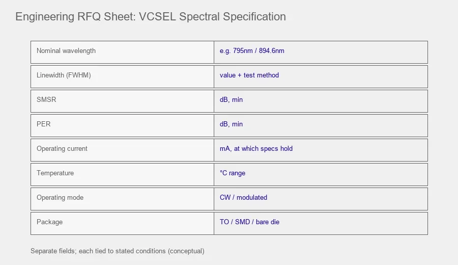
A practical RFQ template
A precision sensing team can use the following structure.
Application
Rb OPM magnetometer using D1 optical pumping
Optical transition
Rb D1 near 795nm
Delivery format
Bare die or project specific nonmagnetic package
Nominal operating point
- Laser temperature: 70 °C
- Forward current: 2.0mA
- Operating mode: CW
Spectral requirements
- Peak wavelength: project defined range around 795nm
- Spectral linewidth: ≤30MHz
- SMSR: ≥35dB
- PER: ≥20dB
- No mode hop within defined current and temperature window
- No polarization switching within defined current and temperature window
Tuning requirements
- Provide wavelength shift versus current
- Provide wavelength shift versus temperature
Test documentation
- State linewidth measurement method
- Provide spectrum at nominal operating point
- State SMSR and PER measurement conditions
- Provide sample level test data where available
Project screening
- Confirm whether tighter linewidth or SMSR screening is available
- State expected yield and minimum order quantity
- State whether screened values can become production acceptance limits
This is clear enough for the supplier to answer with engineering data rather than a generic datasheet.
Example using current application level specifications
Current 1ONELASER product data shows why the requirement should be application specific.
- 795nm typical wavelength
- 0.7mW typical optical power at the stated operating point
- SMSR ≥35dB
- PER ≥20dB
- Spectral linewidth ≤30MHz
- CW operation
- Reference condition around Ta = 70 °C and IF = 2mA
A separate 894.6nm single mode VCSEL bare die for Cs OPM evaluation is published with a different standard set, including:
- SMSR ≥30dB
- PER ≥20dB
- Spectral linewidth ≤50MHz
Neither set should be copied into an unrelated project as a universal atomic sensing standard.
They are examples of how a source can be specified against a particular wavelength, application and operating condition.
For a comparison of optical mode architecture, see Single Mode vs Multimode VCSEL Which Should You Choose.
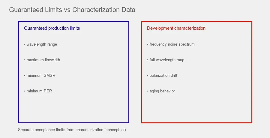
What should be guaranteed and what should be characterized
Not every useful optical parameter needs to become a guaranteed production limit.
This distinction can reduce cost.
Good candidates for guaranteed limits
- Wavelength range
- Optical power range
- Maximum linewidth
- Minimum SMSR
- Minimum PER
- Operating current
- Package dimensions
Good candidates for characterization during development
- Detailed frequency noise spectrum
- Complete wavelength map versus current and temperature
- Sideband spectrum under project specific RF modulation
- Long term polarization drift
- Sensitivity to optical feedback
- Atomic resonance contrast in the customer vapor cell
If a parameter is critical to production acceptance, define it clearly enough for both sides to reproduce the measurement.
If it is only useful during R&D, request characterization data without turning it into an unnecessarily strict lot acceptance requirement
.
Final engineering rule
For a precision VCSEL, linewidth, SMSR and polarization are three different specifications.
Linewidth describes the spectral width and frequency behavior of the main optical mode.
SMSR describes how strongly the dominant mode suppresses unwanted side modes.
PER or an equivalent metric describes how strongly one polarization state dominates the orthogonal state.
A professional RFQ should specify all three only where the application needs them, and every number should be tied to current, temperature, operating mode and a defined measurement condition.
Standard datasheet limits are a starting point. Project specific screening can sometimes tighten wavelength, linewidth, SMSR or polarization requirements, but the achievable combination depends on manufacturing distribution and test yield.
The goal is not to ask for the smallest linewidth and largest SMSR available.
The goal is to define the optical source window that makes the complete atomic clock, magnetometer or precision sensor repeatable.
Frequently Asked Questions
Is SMSR the same as laser linewidth
No. SMSR compares the dominant optical mode with the strongest unwanted side mode. Linewidth measures the spectral width of the dominant emission. A laser can have high SMSR and still have a relatively broad main mode.
What is a good SMSR for an atomic sensing VCSEL
There is no universal value. Published atomic sensing VCSELs and commercial products use different limits depending on wavelength and architecture. Values around 30dB or higher are common reference points for single mode atomic sensing sources, but the system should define its own minimum requirement.
Is a lower linewidth always better
A lower linewidth can improve spectroscopy and reduce some noise mechanisms, but it can also increase component cost or require a different laser architecture. The correct limit should be derived from the required clock or sensor performance.
Why should linewidth be specified at a particular temperature
VCSEL wavelength, optical spectrum and mode behavior depend on junction temperature and current, so any acceptance measurement should identify the controlled package or thermistor temperature used as the test reference. A room temperature linewidth value may not represent a device operated at an elevated temperature for an atomic transition.
Can a supplier screen standard VCSELs for tighter linewidth or SMSR
Sometimes. Project specific screening or binning can be possible when the production distribution contains enough devices meeting the tighter requirement and the supplier has the required test capability. The customer should state the operating point, acceptance method, quantity and required guarantee.
Does single mode automatically mean stable polarization
No. Spatial or spectral single mode operation and polarization stability are separate characteristics. If the system depends on a defined polarization state, specify PER or another polarization criterion separately.
What is the difference between PER and OPSR
Both describe how strongly the wanted polarization dominates the orthogonal one. Polarization extinction ratio, or PER, and orthogonal polarization suppression ratio, or OPSR, are closely related terms used in different datasheets and papers, and the exact measurement setup can differ. For procurement, the important step is to state which metric, which value in dB, and under which current and temperature it must hold, rather than assuming the two labels are interchangeable across suppliers.
Why do conventional VCSELs have a broad linewidth
A VCSEL has a very short optical cavity and high round trip loss, which shortens photon lifetime and raises spontaneous emission relative to longer cavity lasers. As a result, a standard VCSEL often emits with a linewidth above 100MHz. Reaching the single digit or tens of MHz range needed for demanding atomic work requires specific cavity engineering, such as an extended or passive cavity, so a very narrow linewidth is a deliberate design outcome rather than a free feature.
Do I need to specify RIN and modulation bandwidth as well
Only when the system needs them, but then they matter as much as the spectral parameters. A CPT atomic clock that directly modulates the VCSEL at GHz frequencies depends on modulation bandwidth and low relative intensity noise, so both should be defined at the operating point. A simpler absorption sensor operating CW may not need either as a guaranteed limit.”