
940nm
940nm 800mW VCSEL Bare Die
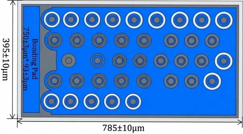
940nm 800mW VCSEL bare die with 44 emitters and 830mW typical output for pulsed NIR illumination, machine vision, OEM packaging and optical modules.
Specifications
- Product Type
- Multi-mode VCSEL Bare Die
- Wavelength
- 940nm typ.; 930nm – 950nm
- Optical Output Power
- 780mW min. / 830mW typ.
- Emitter Configuration
- 44 emitters
- Operating Mode
- QCW / Pulse
- Die Size
- 785±10μm × 395±10μm
- Recommended Assembly
- Die Attach / Wire Bonding / Ceramic Submount / Custom Packaging
1. 940nm 800mW VCSEL Bare Die for Pulsed NIR Packaging and Module Integration
The 940nm 800mW VCSEL Bare Die is a higher-output, multi-emitter, multi-mode VCSEL chip developed for chip-level packaging, ceramic-submount assembly and pulsed near-infrared optical-module integration. The device contains 44 emitters and provides 780mW minimum and 830mW typical optical output at IF = 0.5A under a QCW test condition at 25 °C.
Its 785 ±10μm × 395 ±10μm rectangular die, 44-emitter configuration and 800mW-class output position this model for higher-output pulsed NIR illumination, machine-vision support and custom optical-source development.
This 940nm VCSEL bare die is intended for:
- OSAT semiconductor assembly and test providers
- VCSEL and laser-diode packaging companies
- Die-attach and gold wire-bonding engineering teams
- Ceramic-submount and chip-on-board integrators
- Higher-output NIR optical-module manufacturers
- Pulsed illumination-source developers
- Machine-vision and camera-support companies
- Industrial sensing and inspection companies
- Lens, diffuser and beam-shaping companies
- Laser-component distributors and second-source development teams
As an unpackaged semiconductor die, this product requires suitable die attachment, wire bonding, electrical driving, package protection and optical integration. It is not supplied as a finished SMD device, COB source, packaged laser or complete optical module.
Lead Time: In-stock products are dispatched within 3 business days; custom-packaged products have a lead time of 15–20 days.
MOQ: The minimum order quantity is 1 reel; selected special models support small-batch orders.
2. Optical Configuration and Packaging Direction
The 940nm 800mW VCSEL Bare Die uses a 44-emitter structure for higher-output pulsed near-infrared source development. Its electrical, optical and mechanical parameters must be evaluated under the stated QCW condition, drive current, pulse width, duty cycle and temperature.
Parameter | Value |
|---|---|
Optical Output Power | 780mW min. / 830mW typ. at IF = 0.5A |
Center Wavelength | 940nm typ. |
Specified Wavelength Range | 930nm min. / 940nm typ. / 950nm max. |
Operating Condition | QCW, 0.1ms pulse width, 10% duty cycle, 25 °C |
Emitter Configuration | 44 emitters |
Forward Voltage | 3.25V min. / 3.4V typ. / 3.55V max. at IF = 0.5A |
Threshold Current | 40mA min. / 50mA typ. / 75mA max. |
Differential Resistance | 1.1Ω typ. |
Slope Efficiency | 1.8W/A min. / 2.0W/A typ. |
Power Conversion Efficiency | 47% min. / 52% typ. at IF = 0.5A |
Beam Divergence | 26° min. / 29° typ. / 32° max. at 1/e² |
Emitting Aperture | 14 ±1μm |
Die Size | 785 ±10μm × 395 ±10μm |
Die Thickness | 130 ±10μm |
Anode Pad Size | 750 ±3μm × 93 ±3μm |
Backside Cathode Area | 785 ±10μm × 395 ±10μm |
The device supports conductive die attachment, gold wire bonding, ceramic-submount assembly, chip-on-submount integration and application-specific laser packages. Package design should account for the rectangular die geometry, elongated anode pad, backside cathode, attachment material, current-delivery path, bonding process and optical alignment.
The stated 830mW typical value is a component-level test result under the specified QCW condition. It should not be interpreted as a continuous-wave output rating. Final optical output, wavelength, operating temperature and reliability depend on the completed package, driver, pulse condition, thermal path, optics and module architecture.
3. Packaging, Optical Module and Application Development
OSAT and Custom VCSEL Packaging
The 940nm 800mW VCSEL Bare Die supports die attachment, gold wire bonding, ceramic-submount assembly and custom semiconductor-laser package development. Applicable packaging directions include:
- Rectangular VCSEL die attachment and bond-line evaluation
- Gold wire-bonding process development
- Ceramic-submount assembly
- Chip-on-submount optical sources
- Application-specific ceramic packages
- Pulsed NIR source packages
- Custom VCSEL array packaging
- Higher-output NIR optical modules
The 44-emitter configuration, 0.5A test current, 3.4V typical forward voltage and rectangular die geometry require suitable current delivery, die attachment and package protection. Bond-pad access, backside electrical contact, ESD control, package alignment and thermal behavior must be validated under the stated pulse condition.
Lens and Optical Module Integration
The device can support optical companies and module-development teams working on integrated 940nm near-infrared sources using:
- Collimation-lens assemblies
- Diffuser-integrated optical sources
- Beam-shaping and homogenization components
- Lens-integrated ceramic packages
- Wide-field pulsed NIR illumination sources
- Machine-vision support sources
- Application-specific optical assemblies
Optical integration should be validated using the actual far-field distribution, 29° typical beam divergence, 14μm emitting aperture, rectangular die geometry, package position, lens spacing, diffuser characteristics and complete module architecture. Beam divergence alone does not define the final spot size, irradiance distribution or usable optical field.
Downstream Application Development
The 940nm 800mW VCSEL Bare Die supports component-level development and engineering evaluation for:
- Higher-output near-infrared illumination
- Active optical detection
- Machine-vision support illumination
- Camera-related NIR source development
- Industrial optical detection
- Industrial inspection systems
- Pulsed sensing-source modules
- Engineering and research light sources
- Customer-specific optical modules
These are downstream development directions after the bare die has been integrated into a suitable electrical, mechanical and optical system. The component does not independently establish detection distance, optical uniformity, eye-safety classification, finished-device performance or regulatory approval.
The finished-device developer must independently validate the driver condition, received optical signal, working distance, package temperature, beam distribution, laser classification, electrical safety and complete-system requirements.
Related Articles
4. Evaluation Kit and Documentation Support
The 940nm 800mW VCSEL Bare Die supports rectangular die-attach trials, wire-bonding verification, ceramic-submount development, pulsed driver testing and initial higher-output optical-module integration.
The Evaluation Kit includes 10 pcs / KIT per selected model:
Samples & Pilot Production: Evaluation kits, low-volume pilot production, and pre-production validation are supported.
- 940nm 800mW VCSEL Bare Die
- Corresponding product datasheet
- Corresponding die-dimension documentation
- International shipping quoted according to destination
We offer project-specific support for the following requirements:
- Center wavelength and wavelength tolerance
- Optical output and power-bin selection
- Emitter configuration and chip layout
- QCW driver, pulse width and duty-cycle requirements
- Die attachment, wire bonding and ceramic-submount design
- Thermal path and package configuration
- Lens, diffuser and optical-module integration
- Volume-supply requirements
For component-level project evaluation, an Initial Product Report covering the Laser Diode Series and VCSEL Laser Diode Chip Series has been filed with the U.S. FDA CDRH. This filing supports technical documentation and product evaluation.
For applicable products, CE, EMC, EN 60825, LVD, RoHS, REACH and halogen-free certification and compliance documents are available. Documentation depends on the corresponding product model and does not represent certification of the customer's finished device.
5. Frequently Asked Questions
FAQ 1. What packaging and operating conditions are required for the 940nm 800mW VCSEL Bare Die?
The device is supplied as an unpackaged semiconductor die and requires conductive die attachment, top-side wire bonding, ESD-controlled handling and package-level protection. Its 830mW typical optical output is measured at IF = 0.5A, 25 °C, a 0.1ms pulse width and 10% duty cycle. The package should provide reliable backside cathode contact, suitable access to the elongated anode pad, current delivery and optical alignment. Different current, pulse, temperature or thermal conditions require separate electrical and optical validation.
FAQ 2. When should I select the 940nm 800mW device instead of the 300mW or 1.5W model?
The 800mW model is suitable when the project requires substantially higher pulsed output than the 300mW device and can support its rectangular die, 0.5A drive current and 3.4V typical forward voltage. The 300mW model may be preferred when lower current and a smaller square die are required. The 1.5W model may be more appropriate when watt-level output is required and the package can support a larger emitter array, 2A drive current and greater thermal load.
FAQ 3. Can the 940nm 800mW VCSEL Bare Die be evaluated for illumination and machine-vision projects?
Yes. The device supports component-level evaluation for higher-output pulsed NIR illumination, active optical detection, machine-vision support and industrial inspection. Engineering evaluation should cover the QCW operating condition, optical output, beam divergence, die geometry, package design, lens or diffuser position and working distance. The bare die is not a complete optical system and does not independently determine illumination distance, irradiance distribution, optical safety or finished-product performance. 1ONELASER offers custom packaging and optical integration for qualified projects.