
Sep 30, 2026Technical Insights
VCSEL vs DFB Laser for Atomic Clocks and Precision Sensing
Compare VCSEL and DFB lasers for atomic clocks and precision sensing by linewidth, modulation, optical power, SWaP, packaging and system architecture.
For an atomic clock or precision sensor, a DFB laser is not simply a more accurate VCSEL, and a VCSEL is not simply a cheaper DFB.
They solve different system problems.
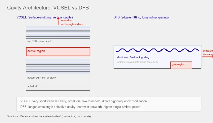
A VCSEL places a very short optical cavity perpendicular to the wafer and emits through the surface. This supports extremely small die size, low threshold current, wafer-level testing and direct high-frequency current modulation.
A DFB laser normally uses an edge-emitting semiconductor cavity with a distributed grating that selects the lasing wavelength along the gain region. That longer wavelength-selective cavity can support much narrower linewidth and higher single-emitter optical power.
Those structural differences create the main tradeoff.
VCSEL is usually strongest when size, power consumption, direct modulation and manufacturability dominate.
DFB is usually strongest when narrow linewidth, optical power and spectral purity dominate and the system can accept a larger or more complex optical source.
For atomic and precision systems, the correct choice depends on the interrogation architecture.
Which VCSEL versus DFB question are you actually asking
There are two very different comparisons that both get called "VCSEL vs DFB," and mixing them leads to the wrong conclusion.
The first is the telecom and datacom comparison. In short-reach optical links, VCSELs at 850nm drive multimode fiber, while DFB lasers at 1310nm or 1550nm drive single-mode fiber over longer distances. That discussion is about data rate, reach, fiber type and cost per bit.
The second is the atomic, quantum and precision-sensing comparison. Here the wavelength is fixed by an atomic transition rather than by a fiber window: roughly 795nm for the rubidium D1 line and roughly 894.6nm for the cesium D1 line. The source drives a vapor cell, and the figures of merit are linewidth, frequency and intensity noise, polarization, direct microwave modulation and package size.
This article is about the second comparison.
If you landed here while designing a fiber link, the tradeoffs below still describe the underlying physics, but the selection priorities for a data-center transceiver are different from those for an atomic clock or a magnetometer.
A DFB laser is also just one specific type of edge-emitting laser. If you are still choosing between surface-emitting and edge-emitting sources in general, rather than specifically weighing a DFB or DBR device, the wider VCSEL vs edge-emitting laser comparison is the better starting point, and this article is the narrow-linewidth, atomic-source companion to it.
Start by separating wavelength accuracy from linewidth
These two ideas are often mixed together.
They should not be.
Wavelength accuracy
Wavelength accuracy asks:
Can the laser be tuned and stabilized on the required atomic or molecular transition
For a rubidium D1 system, that may mean approximately 795nm.
For a cesium D1 system, that may mean approximately 894.6nm.
Both VCSELs and DFB lasers can be designed for specific atomic transitions.
Both can also require temperature and current control to reach the exact line.
A DFB laser does not automatically have the correct atomic wavelength merely because it has a narrow linewidth.
A VCSEL does not automatically have poor wavelength accuracy merely because its free-running linewidth is broader.
Linewidth
Linewidth asks:
How spectrally narrow is the laser emission around its center frequency
Here, conventional DFB lasers often have a clear advantage.
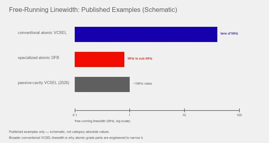
DFB devices used in atomic spectroscopy have demonstrated linewidths of a few MHz and below 1MHz in specialized designs.
Conventional compact atomic-clock VCSELs have often operated with linewidths in the tens of MHz to around 100MHz.
That difference can matter for frequency noise, resonance contrast and high-stability spectroscopy.
This is why the right comparison is:
Can each source reach the correct wavelength, and is its linewidth suitable once it gets there
The architecture explains the difference
VCSEL means vertical-cavity surface-emitting laser.
The optical cavity is perpendicular to the wafer surface and is formed between distributed Bragg reflector stacks.
The cavity is very short.
DFB means distributed-feedback laser.
A periodic grating provides wavelength-selective feedback along the laser cavity, which is commonly implemented in an edge-emitting architecture.
The cavity and feedback geometry are therefore fundamentally different.
That affects:
- optical linewidth
- output power
- threshold current
- beam geometry
- direct modulation
- fabrication
- wafer testing
- packaging
- thermal control
- cost at scale
Neither architecture wins every category.
DFB is not the only edge-emitting narrow-linewidth option: DFB versus DBR
In alkali-atom sources the term "DFB" is often used loosely to mean any narrow-linewidth single-frequency edge emitter, but two closely related architectures appear in this market and they are worth separating.
A DFB laser places the wavelength-selective grating along the active region itself.
A DBR laser places the grating in a passive section next to the gain region, so the grating and the gain are physically separated.
Both are edge emitters, both produce single-frequency narrow-linewidth output, and both are used at alkali D1 wavelengths. For example, commercial 795nm DBR devices are used for rubidium D1 optical pumping and are valued for a wide mode-hop-free tuning range, while DFB diodes are widely used at rubidium and cesium wavelengths for the same class of application.
For procurement, the DFB-versus-DBR distinction rarely changes the top-level VCSEL comparison. The questions that actually matter are the same for either edge-emitter variant: exact center wavelength, linewidth, mode-hop-free tuning range, available optical power, direct-modulation capability at the clock frequency, polarization and package. Where this article says DFB, most of the reasoning also applies to a DBR device, and the safest specification names the required performance rather than assuming DFB and DBR are interchangeable.
A practical comparison
Engineering factor | VCSEL | DFB laser |
|---|---|---|
Emission direction | Surface normal | Typically edge emitting |
Cavity length | Very short | Longer distributed-feedback cavity |
Typical atomic-sensing free-running linewidth | Often tens of MHz to around 100MHz for conventional compact devices, although advanced VCSELs can be much narrower | Often MHz-class or sub-MHz in suitable designs |
Direct GHz current modulation | A major strength of many atomic-clock VCSELs | Device dependent and not guaranteed for an atomic-line DFB |
Threshold current | Often sub-mA to a few mA for low-power atomic VCSELs | Often higher in atomic-line DFB devices, device dependent |
Single-emitter optical power | Often hundreds of μW to low mW in precision single-mode devices | Can be tens of mW in suitable devices |
Beam | Often relatively symmetric | Typically asymmetric edge-emitter beam before optics |
Wafer-level optical testing | Strong manufacturing advantage | More dependent on post-cleave device processing |
Die size | Very small | Usually larger cavity footprint |
2D array integration | Natural | Not a primary architecture advantage |
Precision spectroscopy | Suitable when compactness and modulation dominate | Strong when narrow linewidth and higher power dominate |
Chip-scale CPT clock | Common choice | Possible but may need a different modulation architecture |
Large laboratory spectroscopy setup | Useful but linewidth may be limiting | Often attractive |
Cost potential at volume | Strong because of wafer testing and small die, but specialty atomic wavelength screening still affects cost | Mature in several markets but specialty atomic wavelengths and packaging can be expensive |
Packaging complexity | Can be extremely compact | May require more optical and thermal packaging |
External modulator need | Often avoidable in direct-modulated CPT designs | May be needed if the exact DFB cannot provide required GHz optical modulation |
The words often, can and device dependent are deliberate.
A laser architecture is not a datasheet.
The exact device still has to be checked.
Why DFB lasers usually achieve narrower linewidth
A DFB laser uses distributed wavelength-selective feedback through a grating along the active region.
The longer effective optical interaction and strong mode selection can support narrow single-frequency emission.
Real atomic-spectroscopy examples illustrate the range.
A 780nm DFB used for rubidium spectroscopy reported approximately 4MHz free-running linewidth.
Another GaAs DFB at 780.24nm demonstrated approximately 612kHz linewidth, more than 40dB SMSR and up to 60mW optical power.
A rubidium stabilization experiment reduced a DFB laser from approximately 2MHz to 20kHz using atomic-coherence-based locking.
These are not universal DFB specifications.
They show why DFB is attractive when the experiment is limited by source linewidth.
Why conventional VCSEL linewidth is broader
A conventional VCSEL has a very short cavity and small optical mode volume.
Those characteristics are excellent for compactness and modulation, but they can increase spontaneous-emission-related phase noise and produce a broader free-running linewidth.
In chip-scale atomic clocks, conventional VCSEL linewidths around tens of MHz to approximately 100MHz have been widely used.
This can still be completely practical.
The vapor cell itself may have pressure-broadened optical transitions, and the benefits of low power and direct microwave modulation can outweigh the broader laser spectrum.
Recent research also shows that the linewidth difference is not a permanent architectural law.
A 2026 cesium D1 VCSEL using an integrated passive cavity demonstrated approximately 1MHz intrinsic linewidth with SMSR above 35dB and strong atomic-clock performance.
That is important because it shows the engineering frontier is moving.
The question should therefore be:
What linewidth does the exact VCSEL achieve
not:
Are VCSELs always broad-linewidth lasers
Direct modulation can reverse the system-level decision
If linewidth were the only parameter, many precision systems would choose a DFB.
But atomic clocks often need modulation.
A common Rb-87 CPT clock uses modulation around 3.417GHz.
A common Cs CPT implementation uses modulation around 4.596GHz.
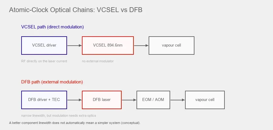
Many clock-oriented VCSELs are deliberately designed for direct current modulation in this GHz range.
The microwave drive changes the laser spectrum and generates the optical sidebands needed for the CPT interaction.
That can eliminate a separate electro-optic modulator.
This is a major system advantage.
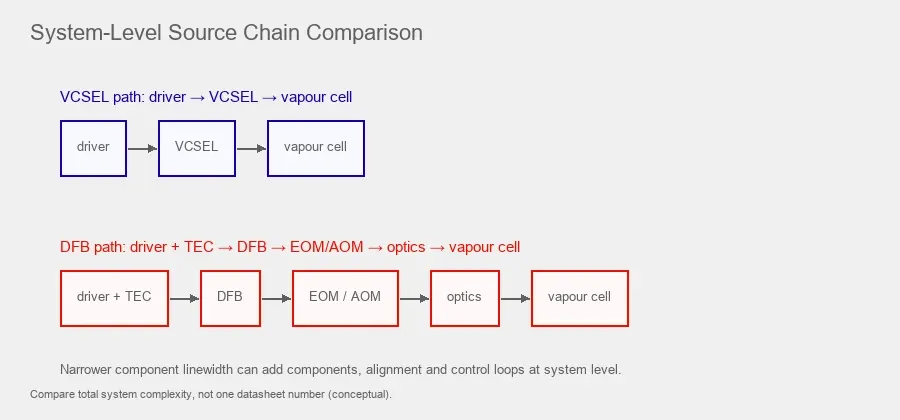
A DFB source may offer a much narrower free-running line but still make the complete clock larger if the required atomic interrogation needs:
- EOM
- AOM
- additional RF electronics
- fiber coupling
- extra optical alignment
- additional bias control
Older cesium-clock research provides a clear example.
A laboratory cesium CPT clock initially used a 894.6nm DFB source with an external electro-optic modulator. Later miniaturization work moved to a directly modulated 894.6nm VCSEL because that architecture was better suited to a compact clock.
The lesson is not that DFB cannot be modulated.
Modern DFB lasers in other markets can support high-speed modulation.
The lesson is that you must verify the exact modulation bandwidth and optical sideband behavior of the atomic-line DFB you intend to use.
Do not assume telecom DFB performance transfers automatically to a specialty 795nm or 894.6nm device.
VCSELs are difficult to beat on size and electrical power
Atomic-grade VCSELs can operate at currents of only a few milliamps or less.
For example, a conventional cesium clock VCSEL can operate around 1.4mA and deliver hundreds of microwatts.
That allows:
- small current drivers
- small thermal packages
- low electrical power
- direct placement near a microfabricated vapor cell
- compact optical stacks
- battery-powered instrumentation
This is one reason VCSELs became central to chip-scale atomic clocks.
Many atomic-line DFB sources require higher drive current and a larger source package than low-power atomic VCSELs.
That may be irrelevant in a rack-mounted laboratory instrument.
It may be decisive in a battery-powered sensor head.
DFB lasers can offer much more optical power
If the system needs several milliwatts or tens of milliwatts of clean single-frequency light, DFB becomes attractive.
Atomic spectroscopy research has used DFB sources with tens of milliwatts of output.
This gives more margin for:
- beam splitting
- multiple cells
- pump and probe paths
- fiber distribution
- larger beam diameters
- losses through isolators and modulators
A low-power single-mode VCSEL may only produce a few hundred microwatts.
For a microcell, that can be enough.
For a multi-channel laboratory setup, it may not be.
This is why optical power should be specified at the target, not compared as a prestige number.
Beam geometry changes the optical design
A VCSEL emits approximately perpendicular to the wafer surface.
Low-power single-mode devices often produce a relatively symmetric beam.
That can simplify a compact vertical optical stack.
A DFB is usually an edge emitter.
Its native beam tends to be more asymmetric in fast and slow axes, so collimation often requires more deliberate optics.
In a laboratory system this is routine.
In a millimeter-scale physics package, every lens and alignment degree of freedom matters.
The mechanical architecture can therefore choose the laser before the linewidth discussion is finished.
Wafer-level testing changes manufacturability
Surface emission gives VCSELs an important manufacturing advantage.
A VCSEL can be optically probed and mapped while still on the wafer.
That allows manufacturers to characterize wavelength, power and other properties before dicing and packaging.
For high-volume manufacturing, this can reduce the cost of finding bad devices late in the process.
It also supports:
- wafer maps
- automated binning
- dense device layouts
- two-dimensional arrays
- statistical screening
DFB and other edge-emitting devices usually need additional processing, including cleaving the emitting facets, before full optical device testing.
That does not mean DFB manufacturing is inefficient.
DFB lasers are manufactured at enormous scale in telecom and sensing markets.
It means the VCSEL structure has a structural advantage for wafer-level optical screening.
That becomes useful when a project wants to screen many dies for a narrow wavelength or spectral window.
VCSEL cost is an architecture advantage, not a promise that every atomic VCSEL is cheap
It is common to say VCSELs are cheaper.
That statement needs context.
At high volume, VCSELs can benefit from:
- wafer-level testing
- small die area
- batch processing
- simple surface-emission geometry
- compact packages
These features support low unit cost.
But an atomic-grade VCSEL at 795nm or 894.6nm is not the same commercial situation as a mass-market 940nm sensing array.
Tight requirements on:
- wavelength
- linewidth
- SMSR
- PER
- temperature group
- modulation bandwidth
can reduce yield.
Custom screening adds test cost.
Low-volume research quantities also change the economics.
The better statement is:
VCSEL architecture has strong manufacturing and cost potential, especially at scale, but specialty atomic-source pricing is determined by wavelength, yield, screening and package requirements.
DFB cost also depends on the market
DFB technology is mature.
In telecom wavelengths, large established manufacturing ecosystems exist.
At specialty alkali wavelengths such as 780nm, 795nm or 894.6nm, the available product range is narrower.
The cost of a complete DFB source can also include:
- butterfly or TO packaging
- TEC
- thermistor
- optical isolator
- fiber pigtail
- precision driver
- EOM or AOM if required
- polarization control
For a laboratory spectroscopy system, those costs may be acceptable.
For a chip-scale clock, they can dominate the physical and cost budget.
Compare complete source subsystems rather than bare laser prices.
Wavelength control should be compared as a tuning budget
Engineers sometimes ask which architecture has better wavelength precision.
That question is too broad.
A more useful metric is the tuning budget.
For each source, determine:
- 1. Factory center wavelength
- 2. Manufacturing tolerance
- 3. Temperature tuning coefficient
- 4. Current tuning coefficient
- 5. Mode-hop-free range
- 6. Controller resolution
- 7. Long-term aging
- 8. Available locking signal
Then ask whether the atomic transition falls comfortably inside that tuning space.
A VCSEL designed for 894.6nm can be temperature-binned so the Cs D1 line is reached at a desired setpoint.
A DFB can also be temperature and current tuned and then locked to a vapor-cell reference.
Both architectures can achieve excellent wavelength placement.
The main difference is usually in spectral linewidth, modulation and system size rather than the abstract ability to “hit the wavelength.”
DFB aging can matter in long-lived clocks
Atomic clocks are not one-hour experiments.
Laser aging matters.
Research on 780nm DFB devices for rubidium atomic clocks found a measurable change in the injection current required to maintain resonance over months of operation.
That does not make DFB unsuitable.
It shows why a precision system needs enough current and temperature tuning margin to compensate long-term drift.
The same system-level thinking applies to VCSELs.
For either source, a production design should consider:
- aging
- wavelength drift
- output-power drift
- package stress
- temperature-controller range
- current-controller range
- lock acquisition margin
A narrow linewidth at day one is only part of the lifetime requirement.
Polarization should not be assumed from architecture
Atomic clocks and magnetometers often require a defined polarization state.
A VCSEL may have strong linear polarization, but polarization switching can occur with current, temperature or mounting stress.
A DFB can also require polarization characterization, especially once fiber, isolators or external modulators are added.
For either source, define:
- PER
- polarization axis
- stability versus current
- stability versus temperature
- behavior after packaging
- behavior after fiber coupling
The atom sees the delivered polarization, not the laser architecture name.
The correct choice changes with the atomic-clock architecture
Chip-scale CPT clock
VCSEL is usually the first source to evaluate.
Why:
- extremely small source
- low current
- low power consumption
- direct GHz modulation
- compact vertical optical stack
- strong precedent in CSAC development
A DFB may improve linewidth but can increase modulation and packaging complexity.
Higher-stability laboratory CPT clock
DFB, DBR, ECDL or newer narrow-linewidth VCSEL architectures may deserve evaluation.
Why:
- linewidth-induced noise can become a limiting factor
- size is less constrained
- external modulators may be acceptable
The tradeoff shifts from SWaP toward stability.
Optically pumped magnetometer
Both can be valid, and current SERF magnetometer literature treats VCSELs and DFB lasers as the two prevalent pump-source options.
VCSEL is attractive for the sensor head because of small size, low power and compact packaging. That is why VCSELs have become the predominant choice for commercial-grade miniature magnetometers, typically at 795nm for the rubidium D1 line.
DFB is attractive when higher optical power, lower noise or narrower linewidth is worth routing light through fiber from a remote source, which is why DFB sources continue to appear in research systems where optical power and spectral control are priorities.
Two magnetometer-specific requirements sit on top of the usual clock criteria and can override the linewidth discussion entirely.
First, the pump source near the vapor cell should be non-magnetic. A sensitive magnetometer, especially a spin-exchange-relaxation-free (SERF) sensor, resolves fields at the nanotesla level or below, so ferromagnetic package metals, platings or fasteners can distort the local field and the atomic lock point. This favors whichever architecture can be delivered in a genuinely non-magnetic package, and it is often easier to place a compact non-magnetic VCSEL directly at the sensor head while a remote DFB is fiber-coupled in from outside the shield.
Second, both frequency stability and intensity stability of the pump light are critical. Pump-light frequency and intensity fluctuations can couple into the magnetometer output and contribute to equivalent magnetic-field noise, with the exact coupling depending on detuning, light shift, cell conditions and the detection architecture. The source should therefore be specified with defined frequency-noise and relative-intensity-noise limits, not only a center wavelength and linewidth.
Atomic spectroscopy bench
DFB is often a strong starting point.
A laboratory usually has room for collimators, isolators, fiber and temperature control.
Narrower linewidth and higher optical power can be more valuable than the smallest possible source.
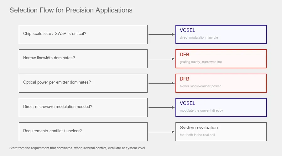
A decision table for precision applications
Project priority | Start by evaluating |
|---|---|
Minimum source volume | VCSEL |
Minimum electrical power | VCSEL |
Direct 3 to 5GHz current modulation | VCSEL |
Wafer-level screening and compact OEM integration | VCSEL |
Narrow free-running linewidth | DFB |
High single-frequency optical power | DFB |
Multi-path laboratory spectroscopy | DFB |
Chip-scale CPT clock | VCSEL |
Research clock limited by laser frequency noise | DFB or another narrow-linewidth source, while also evaluating advanced narrow-linewidth VCSELs |
Compact OPM sensor head | VCSEL |
Remote laser with fiber-fed OPM | DFB can be attractive |
Highest possible integration with no external modulator | VCSEL is often easier |
Existing optical system already designed around fiber and EOM | DFB may fit naturally |
This is a starting matrix, not a winner table.
A modern narrow-linewidth VCSEL changes the old comparison
The traditional comparison says:
VCSEL means compact but broad linewidth
DFB means narrow linewidth but larger system
That description is becoming less complete.
In 2026, a research VCSEL at the Cs D1 line demonstrated approximately 1MHz intrinsic linewidth using a monolithically integrated passive cavity.
The device also reported:
- SMSR above 35dB
- strong polarization suppression
- approximately 7° beam divergence
- operation in a cesium clock testbed
This does not mean every commercial VCSEL now has 1MHz linewidth.
It means the architecture is evolving.
For future designs, engineers should compare current datasheets instead of relying on a ten-year-old category stereotype.
DFB is also not one fixed performance class
The same warning applies to DFB lasers.
One DFB may have:
- sub-MHz linewidth
- tens of milliwatts output
- limited modulation at the required clock frequency
Another may be designed for telecom and support high-speed direct modulation.
Another may be optimized for gas sensing.
Another may only be available at wavelengths far from the atomic line.
So a procurement specification should never say:
Need DFB because DFB is narrow linewidth
It should say:
- target wavelength
- linewidth limit
- output power
- tuning range
- modulation requirement
- package
- thermal control
- polarization
- noise
- size and power budget
Then compare actual devices.
How to write the RFQ
A useful source-selection RFQ for an atomic system can use the following structure.
Atomic system
Rb-87 D1 or Cs-133 D1
Architecture
CPT clock, microwave clock, OPM or spectroscopy system
Wavelength
Target center wavelength and required tuning margin
Linewidth
Maximum acceptable linewidth and measurement condition
Optical power
Power required at the cell
Modulation
Exact RF or low-frequency modulation requirement
Polarization
PER and stability requirement
Thermal control
Operating setpoint and ambient range
Size
Maximum source and package dimensions
Electrical budget
Maximum current and total source power
Package
Bare die, TO-can, butterfly, fiber-coupled or other
Production
Prototype quantity, qualification quantity and forecast volume
Then ask the supplier to recommend VCSEL, DFB or another laser architecture against the complete requirement.
That produces a better result than specifying the architecture first.
When a VCSEL is the better engineering choice
In short, choose a VCSEL when the system gains real value from a very small die and package, low threshold and operating current, direct microwave modulation, a vertical optical layout, low total source power and wafer-level screening for high-volume compact integration. This is why VCSEL remains the reference architecture for many chip-scale atomic clocks. On the product side, 1ONELASER provides 795nm and 894.6nm single-mode VCSELs for rubidium and cesium vapor-cell systems, including bare-die evaluation and project-specific TO-46 thermal-control configurations; see the Atomic Clock and OPM Magnetometer Solution for the platform overview.
When a DFB or DBR laser is the better engineering choice
Choose an edge-emitting DFB or DBR source when the system benefits more from narrower free-running linewidth, higher single-frequency power, an established fiber-coupled architecture, more optical margin for splitting or attenuation, or laboratory-scale frequency stabilization, and can accept an external modulator if required. It is especially attractive when the precision limit is set by laser frequency noise rather than by source size or power consumption.
Do not choose from component specifications alone
The best atomic source is the one that produces the best system discriminator.
For a clock, compare:
- CPT contrast
- CPT linewidth
- error-signal slope
- light shift
- FM-to-AM noise
- Allan deviation
- warm-up
- power consumption
For a magnetometer, compare:
- optical pumping efficiency
- resonance linewidth
- signal amplitude
- magnetic sensitivity
- laser-induced magnetic noise
- polarization stability
- sensor-head volume
A laser can look better on a standalone spectrum analyzer and still make the complete instrument worse.
Final engineering rule
VCSEL and DFB optimize different parts of the precision-laser problem.
A conventional VCSEL gives up some linewidth in exchange for exceptional size, low current, direct modulation and integration.
A DFB often gives narrower linewidth and higher optical power but may require more packaging, current, optics or external modulation.
For a chip-scale CPT clock, that system complexity often favors the VCSEL.
For a laboratory clock or sensor whose performance is limited by laser frequency noise, the balance can move toward DFB or another narrow-linewidth source.
The decision should therefore be made in this order:
atomic transition → interrogation method → linewidth target → modulation requirement → optical power → SWaP → manufacturing and cost
Not:
VCSEL or DFB first
A DFB laser is one specific type of edge-emitting laser, so this article is the narrow-linewidth, single-frequency companion to the broader architecture comparison rather than a duplicate of it.
Related reading: the VCSEL vs edge-emitting laser comparison for the general surface-emitting versus edge-emitting choice; what VCSEL a chip-scale atomic clock needs for CSAC source requirements; and the 894.6nm / 895nm VCSEL for cesium atomic clocks article for a worked V00140 second-sourcing example.
Frequently Asked Questions
Is a DFB laser more wavelength accurate than a VCSEL
Not automatically. Both can be designed and tuned to a specific atomic wavelength. DFB lasers often provide narrower linewidth, but center-wavelength accuracy still depends on manufacturing tolerance, temperature, current tuning and frequency locking.
Is a DFB laser always narrower than a VCSEL
Conventional atomic-sensing DFB devices often have narrower linewidth than conventional compact VCSELs. However, advanced narrow-linewidth VCSEL architectures have demonstrated linewidths around the MHz level, so the exact devices should be compared rather than relying only on architecture.
Why are VCSELs common in chip-scale atomic clocks
They combine very small size, low operating current, surface-normal emission and direct GHz current modulation. Those properties reduce the number of optical and RF components needed in a compact CPT clock.
Can a DFB laser be directly modulated for an atomic clock
Some DFB lasers support high-speed modulation, but this is device dependent. A specialty atomic-line DFB should be tested at the exact clock frequency. If it cannot generate the required optical sidebands directly, an EOM or AOM may be needed.
Which laser is cheaper
There is no universal answer. VCSELs have strong wafer-level manufacturing and testing advantages, but atomic-wavelength devices may require low-volume fabrication and tight screening. DFB cost depends strongly on wavelength, package, TEC, fiber coupling and whether external modulation is required.
Which source is better for an optically pumped magnetometer
VCSEL is attractive for a compact sensor head because of size and power consumption, and VCSELs are the predominant choice in commercial miniature magnetometers. DFB can be attractive when narrower linewidth or higher optical power is more important and the laser can be located remotely with fiber delivery. For a sensitive magnetometer, also require a non-magnetic package and defined frequency-noise and intensity-noise limits, because pump-light frequency and intensity fluctuations can couple into the magnetometer output and contribute to equivalent magnetic-field noise.
Is the VCSEL versus DFB comparison the same for telecom and for atomic clocks
No. In telecom and datacom the wavelength is set by the fiber window (for example 850nm multimode VCSELs versus 1310 or 1550nm single-mode DFB) and the priorities are data rate, reach and cost per bit. In atomic systems the wavelength is fixed by an atomic transition (about 795nm for rubidium D1 or 894.6nm for cesium D1) and the priorities are linewidth, noise, polarization, direct microwave modulation and package size. The underlying device physics is shared, but the selection criteria are different.
What is the difference between a DFB and a DBR laser for atomic clocks
Both are edge-emitting single-frequency lasers with narrow linewidth. A DFB places the wavelength-selecting grating along the active region, while a DBR places it in a separate passive section. Both are used at alkali D1 wavelengths; DBR devices are common at 795nm for rubidium and are valued for wide mode-hop-free tuning. For selection the distinction rarely changes the top-level VCSEL comparison, and the specification should state the required wavelength, linewidth, tuning, modulation, power and package rather than assuming DFB and DBR are interchangeable.