
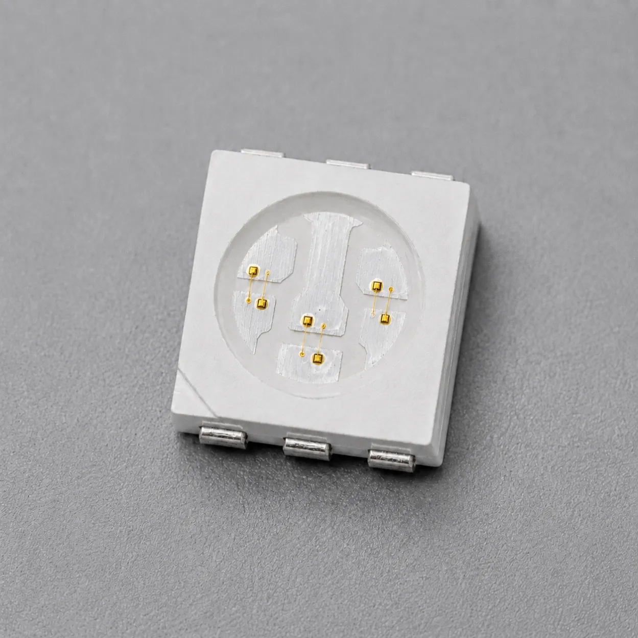
520nm+660nm+940nm
520nm LED / 660nm VCSEL / 940nm VCSEL SMD 7016 (Lower Output)
Lower-output 520nm LED / 660nm VCSEL / 940nm VCSEL 7016 SMD for component-level reflective PPG optical integration, evaluation and OEM engineering support.
Specifications
- Product Type
- Three-Channel LED + VCSEL SMD
- Wavelength Channels
- 520nm LED; 660nm VCSEL; 940nm VCSEL
- Optical Output Power
- 520nm LED: 35mcd typ. (IF=20mA); 660nm VCSEL: 5.5mW typ. (IF=15mA); 940nm VCSEL: 7mW typ. (IF=10mA)
- Emitter Configuration
- One green LED channel, one red VCSEL channel and one infrared VCSEL channel
- Operating Mode
- Continuous-wave (CW), source-specified test conditions
- Optical Emission Profile
- Green LED: 120° full viewing angle; red and infrared VCSEL: 20° full-angle divergence, under source-stated CW conditions
- SMD Package Options
- Six-pin, water-clear 7016 SMD package
1. 520nm LED / 660nm VCSEL / 940nm VCSEL SMD 7016 for Component-Level Reflective PPG Optical Integration
This lower-output 7016 SMD combines a green LED channel, a 660nm red VCSEL channel and a 940nm near-infrared VCSEL channel in a six-pin package for component-level reflective PPG optical-system evaluation. It is an optical emitter component, not a PPG sensor or a finished wearable device.
System accuracy, physiological interpretation, safety and regulatory suitability depend on the completed device and must be validated by the device manufacturer.
Lead Time: In-stock products are dispatched within 3 business days; custom-packaged products have a lead time of 15–20 days.
MOQ: The minimum order quantity is 1 reel; selected special models support small-batch orders.
Contact 1ONELASER To Discuss 520nm LED / 660nm VCSEL / 940nm VCSEL SMD 7016 Integration Requirements
2. Multi-Wavelength Optical Configuration and Channel Selection
The supplied lower-output source table lists the green LED at 515/520/525nm with 30/35/40mcd at IF=20mA, the red VCSEL at 655/665/675nm with 4/5.5/7mW at IF=15mA, and the infrared VCSEL at 930/940/950nm with 6/7/8mW at IF=10mA.
The green LED is specified with a 120° full viewing angle at CW, IF=20mA and Ta=25 °C. The red and infrared VCSEL channels are specified with 20° full-angle divergence under their separately stated CW test conditions.
3. 7016 Package, Electrical Interface and PCB Integration
The source identifies a six-pin, water-clear 7016 SMD package. Its final electrical interface, channel drive arrangement, PCB layout, thermal path and optical coupling should be reviewed for the completed assembly.
Use the source-stated channel values and their different test currents during engineering evaluation. Do not combine those values into an unsupported system-level performance claim.
4. OEM Optical-System Development and Custom Integration
Use this lower-output configuration when an OEM design requires the stated green, red and near-infrared emitter combination for component-level reflective PPG optical integration. Provide the target optical path, driver constraints, mechanical stack-up and operating conditions for engineering review.
Related Articles
5. Evaluation, Documentation and Custom Development Support
This 520nm LED / 660nm VCSEL / 940nm VCSEL SMD 7016 lower-output configuration is available as an Evaluation Kit with 10 pcs / KIT for early-stage review of channel drive, PCB integration, optical coupling and reflective PPG optical-system architecture.
Samples & Pilot Production: Evaluation kits, low-volume pilot production, and pre-production validation are supported.
For component-level project evaluation, an Initial Product Report covering the Laser Diode Series and VCSEL Laser Diode Chip Series has been filed with the U.S. FDA CDRH. This filing supports technical documentation and product evaluation.
For applicable products, CE, EMC, EN 60825, LVD, RoHS, REACH and halogen-free certification and compliance documents are available. Documentation depends on the corresponding product model and does not represent certification of the customer's finished device.
6. Frequently Asked Questions
Is this 7016 SMD a reflective PPG sensor?
No. It is a component-level multi-wavelength optical emitter. Sensor design, signal processing, accuracy, safety and any finished-device requirements must be validated by the device manufacturer.
What source-stated values apply to the 520nm, 660nm and 940nm center channels?
The source table lists 35mcd at IF=20mA for the 520nm green LED, 5.5mW at IF=15mA for the 660nm red VCSEL and 7mW at IF=10mA for the 940nm infrared VCSEL.
Why should the channel test currents be kept separate?
The supplied source table uses different test currents for the green LED, red VCSEL and infrared VCSEL. Preserve those conditions when comparing source values and evaluating the completed optical system.