
Oct 6, 2026Technical Insights
Laser vs LED for Red Light Therapy Devices
Laser vs LED red light therapy: where a VCSEL wins on irradiance, where it loses on efficiency, and how to design out the ring.
The laser vs LED red light therapy comparison usually opens with efficiency. At red wavelengths that is the one argument a VCSEL loses. Center wavelength consistency is largely a purchasing and bin-selection decision. What is left is the argument that actually decides devices: a VCSEL puts sixty to a hundred times the irradiance on target, and then hands you a uniformity problem an LED never had, because a single VCSEL emits a ring with a dim center. This article covers which claims hold, which do not, and how to design the ring out.
Start with the claim that does not survive contact
Efficiency is where most VCSEL pitches open. At red wavelengths it is the argument a VCSEL loses, and it is worth saying so before anything else in this comparison is believed.
Work the 660nm spec table and a red VCSEL lands near 20% wall-plug: roughly 5mW of light out of about 25mW of electrical power in. Now look at what the other side does. Deep-red LEDs are among the most efficient emitters anyone makes, which is why horticulture lighting is built on them. Cree publishes its XLamp XP-L Photo Red S Line, a 660nm horticulture part, at 83.5% wall-plug efficiency at 700mA and 25 °C. That is not a close contest, and no amount of framing makes it one.
The high VCSEL efficiency figures in circulation, 37% and up, are real. They belong to near-infrared parts, where the material system is kinder. Quoting them in a red light context is a category error, and an engineer who checks will find it. If someone is selling you a red VCSEL on efficiency at 660nm, they are quoting the wrong wavelength or an unflattering LED.
So do not buy on efficiency. Two arguments do survive at red, and one of them decides most designs.
Where the wavelength argument is real, and where it is not
This one has two halves, and most comparisons collapse them into one. They are different things, and only one of them is a technology difference at all.
The first half is spectral width, and it is not a specification so much as a consequence of what the two devices are. Stimulated emission in a cavity is narrow, so a red VCSEL emits a line on the order of one to a few nanometers. An LED emits by spontaneous recombination, which is broad by construction: a red LED runs roughly 15 to 30nm wide at half maximum. Call something a 660nm LED and it is emitting across that whole span at once. Laser is not one thing here, and linewidth varies with device type and mode structure, but the gap against a broadband emitter holds either way.
The second half is center wavelength tolerance across a production run, and here the honest answer is that center wavelength consistency across production lots is largely a purchasing and bin-selection decision rather than a technology gap. Both sides bin. The 660nm VCSEL series lists tolerance as model-specific, with center wavelength, tolerance, and power bin all specifiable per project. LEDs bin too, and they bin well: a cheap bin can wander ±20nm, while medical-grade red LED binning reaches ±2 to ±3nm. Specify the bin on whichever side you buy. If you do not, two reels of nominally identical parts will center in different places and nothing on the front panel will tell you.
Now the part that decides how much any of this matters. Cytochrome c oxidase absorbs in bands rather than at a single line, and the red response region reported in the literature is broad, roughly 620 to 680nm. A binned 660nm LED emitting from 645 to 675nm is sitting inside that window. So if your protocol is built on a band, the LED spread is already in the band and the laser buys you little. If your protocol is built on one wavelength, or you need every unit to deliver the same thing at the same place on the curve, the laser largely removes one variable that wavelength binning alone cannot address: emission linewidth. Only that one. A laser center wavelength still moves with junction temperature and drive current, so thermal design owns part of the answer on either side. What binning cannot reach is the width of the line itself. Which wavelength to aim at in the first place is covered in our wavelength selection guide.
Either way, this is not where the decision gets made. Photobiomodulation follows a biphasic dose response, so what reaches the tissue matters more than which nanometer it arrived on. That points at the next section.
Where the irradiance argument is real
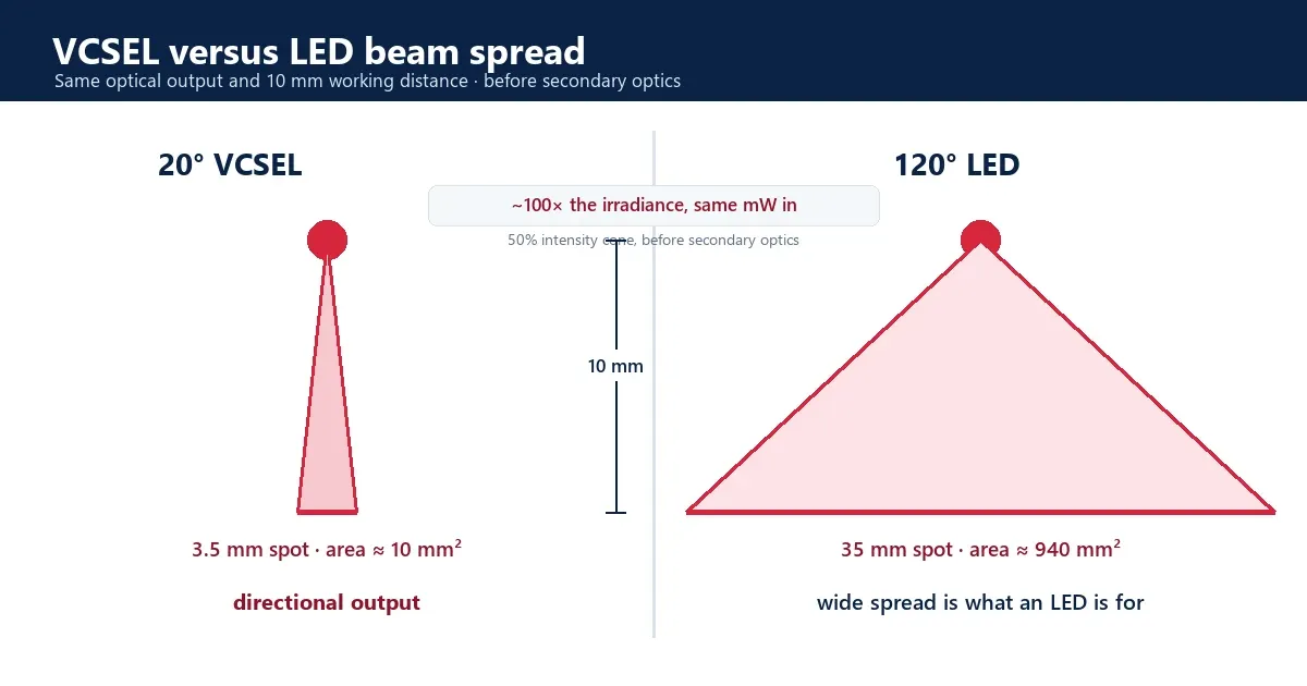
Take the 50% intensity cone for each device. Divergence is not one number across the red band: the 660nm SMD series runs 18° to 20°, the 680nm series 19° to 25°, and the 650nm series 25° typical. A bare LED is Lambertian, which puts its half-intensity full angle at 120° by definition. Both sides move with package and secondary optics, and a lensed or narrow-angle LED is not a bare Lambertian one, so what follows compares two common starting points rather than stating a law.
At a 10mm working distance a 20° part fills a 3.5mm spot against the LED’s 35mm. The areas are about 10mm² and 940mm². Same optical power in, roughly a hundred times the irradiance at the target, before any secondary optics on either side. Take the widest red part at 25° and the spot grows to 4.4mm and the ratio falls to about sixty. That is the honest floor of this argument, and it is still not a close contest.
That number does real work in a design. It means a VCSEL reaches a target irradiance with far fewer milliwatts, which shows up as battery life and as heat you do not have to move. It also means the LED is throwing most of its output somewhere other than the treatment area, which is not a failure of the LED. Wide emission is what an LED is for. It is the wrong tool when the dose at a specific depth is the whole point. The 660nm VCSEL SMD series is specified at 18° to 20° for exactly that reason.
The beam shape argument, and the edge emitter
The third advantage only shows up against the other kind of laser.
An edge-emitting laser diode emits from a rectangular facet, so its far field is elliptical and astigmatic: two different divergences on two axes, and two different apparent source positions. Correcting that takes cylindrical optics or a compromise. A VCSEL emits from a circular aperture through the top surface, so the far field is generally rotationally symmetric, although the detailed mode pattern depends on aperture design. One divergence figure, one lens, done.
The package splits along the same line. Edge emitters arrive in TO-can packages with legs, which means hand insertion, lead trimming, and hand soldering on a board carrying dozens or hundreds of light sources. A VCSEL comes as a surface-mount part that goes down with everything else on the board.
One VCSEL is not uniform, and that is the real trade
The sales version leaves this out. An engineer finds it in the first hour with an evaluation kit.
Multimode VCSEL designs, including the red parts referenced here, produce an annular, doughnut-shaped far field with reduced intensity near the optical axis rather than a filled disc. Shine one at a card and you see a ring. Far-field profile depends on aperture, mode structure, drive current, and any optics, so confirm it for the part you are designing with.
The irradiance advantage has a price, and this is where it gets paid. The LED’s 120° spread, the thing that makes it inefficient at delivering dose, is also the thing that makes an LED array blend itself. Neighboring emitters overlap so heavily by the time light reaches skin that uniformity arrives without anyone designing it. Narrow the beam to 20° and that stops happening for free.
So the honest statement of the trade is short. An LED gives you uniformity for free and control never. A VCSEL gives you control and hands you the uniformity problem. Anyone who tells you the VCSEL beam is more uniform than an LED’s has it backwards at the single-emitter level. The uniformity is real, but it is a property of the array, not of the part.
How to design the ring out
This is the work, and it is neither hard nor optional.
Set pitch from the beam, not by eye. Spot diameter goes as 2 × working distance × tan(divergence ÷ 2). Neighboring rings overlap and fill each other’s dim centers when the pitch is no larger than the spot at your working distance. The emitter pitch math is worked through separately. The shape of it is one line:
Working distance | Spot diameter (18°–20°) | Pitch that overlaps |
|---|---|---|
5mm | ~1.6–1.8mm | ≤ 1.6mm |
10mm | ~3.2–3.5mm | ≤ 3.2mm |
20mm | ~6.3–7.1mm | ≤ 6.3mm |
30mm | ~9.5–10.6mm | ≤ 9.5mm |
Stagger the grid. Rings on a square grid leave a dark spot in the middle of every four. Hexagonal packing puts six neighbors around each ring instead of four, and it costs nothing but a layout decision.
Add a diffuser or a micro-lens array when the pitch will not come down. It works, and it is honest about the price: some output goes into the diffuser instead of the patient.
Let the tissue finish the job, but only knowingly. Skin scatters, so the field at 2mm depth is smoother than the field at the surface. That is real and you can use it. It is not a reason to skip the measurement, because scattering does not rescue a field that arrived as isolated dots.
Then measure the field, not the arithmetic. The pitch table above tells you where to start. Required overlap should be confirmed with a measured irradiance map at your real working distance rather than a calculated spot diameter alone. A ring pattern is obvious on an imaging sensor or a piece of thermal paper, and it is invisible in an averaged irradiance figure. The averaged figure is what lands in your report, and it is the one thing that will not warn you.
Confirm the divergence definition before you build. Divergence can be quoted as a full angle or a half angle, at 1/e² or at FWHM. Every number in the table above assumes a full angle. A factor-of-two error here does not show up in review. It shows up as a striped device.
When an LED is still the better choice
The work in the last section is real, and it is not always worth carrying.
If the goal is to cover a large area at short range with the least optical design effort, an LED array is the simpler and cheaper answer, and it will draw less at the wall besides. The wide divergence that costs an LED its irradiance is the same property that makes an array blend itself, and at short range over a large treated area that is most of what the design needed. Specify the bin, set the spacing, and the job is done.
The engineering overhead of a VCSEL earns its place when one of three things becomes a limiting constraint: irradiance at a target depth, delivered dose that has to repeat unit to unit, or a working distance and emitter pitch that a wide emitter cannot hold. If none of those is binding on your design, the honest recommendation is the LED.
Which one for hair growth
The scalp is the case where the comparison stops being academic, because the market already ran the experiment.
A systematic review of FDA-cleared home-use devices identified 32 such low-level light therapy devices as of January 2020, and cleared devices have clustered on red laser diodes at roughly 635, 650, and 655nm. The follicle bulge and dermal papilla sit roughly 1.5 to 4mm below the scalp, which is within reach of visible red, and hair itself is an optical barrier that takes a share of the light before skin ever sees it. That combination rewards a source that puts its output down rather than sideways, and it punishes a broad emitter.
For a component decision that maps onto the red band directly. The 650nm VCSEL SMD series sits where most cleared hair devices have sat and is where surface-mount parts replace legacy TO-can red laser diodes on a cap or comb carrying a hundred sources. The 680nm VCSEL SMD series sits at the top of the visible-red window for scalp designs that want slightly more penetration or higher output per position.
Whichever way the comparison lands for your device, the ring is what decides whether it works, and no datasheet settles that. The usual sequence is to place a small array on a real board at the real working distance and measure the field before committing a layout. Evaluation kits are one practical way to do that. 1ONELASER develops red VCSEL light-source solutions across 650 to 680nm, as surface-mount packages across the band and as bare die at 660 and 680, with custom package and array options where a catalog part cannot deliver the field a design needs. That is the kind of project we typically support.
One boundary, because this market attracts loose language. The emitter is a component. The finished-device manufacturer remains responsible for optical-dose validation, irradiance and exposure planning, thermal design, laser-safety classification, applicable photobiological risk assessment, product testing, labeling, and every clinical or marketing claim. Standards such as EN 60825-1 may be relevant to laser product classification depending on the finished product and jurisdiction. Choosing a laser over an LED changes the light. It does not clear a device.
FAQ
Is a laser better than an LED for red light therapy?
For a device where dose at a specific depth is the point, a laser gives you one thing an LED cannot: a narrow beam that puts sixty to a hundred times the irradiance on the target instead of the room, depending on the part. It loses on efficiency, and on wavelength it is close to a wash once both sides are binned. An LED gives you uniformity without engineering it, and a VCSEL makes you build that yourself. Neither is better in the abstract.
Is VCSEL more efficient than LED?
At visible red wavelengths, no. A red VCSEL lands near 20% wall-plug, while deep-red LEDs are among the most efficient emitters made and Cree publishes a 660nm horticulture part at 83.5%. The 37% and higher VCSEL figures often quoted belong to near-infrared parts, where the material system is kinder. At 660nm, efficiency is a reason not to switch, not a reason to.
Why does a VCSEL produce a ring instead of a spot?
A multimode VCSEL emits an annular, doughnut-shaped far field with a dim center. It is normal for the device type. Uniform illumination comes from the array: emitters on a pitch no larger than the spot at your working distance, so neighboring rings overlap and fill each other’s centers, with a diffuser or micro-lens array if the pitch cannot come down.
VCSEL or edge-emitting laser for a red light device?
An edge emitter’s far field is elliptical and astigmatic, so it needs cylindrical correction, and it arrives in a TO-can package that has to be hand inserted and hand soldered. A VCSEL is circularly symmetric, which simplifies the optics, and it is a surface-mount part that goes down with the rest of the board.
What emitter pitch do I need for a VCSEL array?
Spot diameter ≈ 2 × working distance × tan(divergence ÷ 2). At the 660nm series divergence of 18° to 20° and a 10mm working distance that is roughly 3.2 to 3.5mm, so a pitch of about 3mm lets rings overlap. Other red parts differ: at the 650nm series 25° the same distance gives 4.4mm. Run your own part figure, and check whether your datasheet quotes a full or half angle before building to it.
Laser or LED for a hair growth device?
A systematic review of FDA-cleared home-use devices identified 32 such low-level light therapy devices as of January 2020, and cleared devices have clustered on red laser diodes at roughly 635, 650, and 655nm. A cap or comb carries many sources through hair to a follicle a few millimeters down, which rewards a narrow beam and a tightly held wavelength. The device maker validates the finished product and owns any clinical or regulatory claim.