
905nm
905nm Multi Junction VCSEL SMD Series
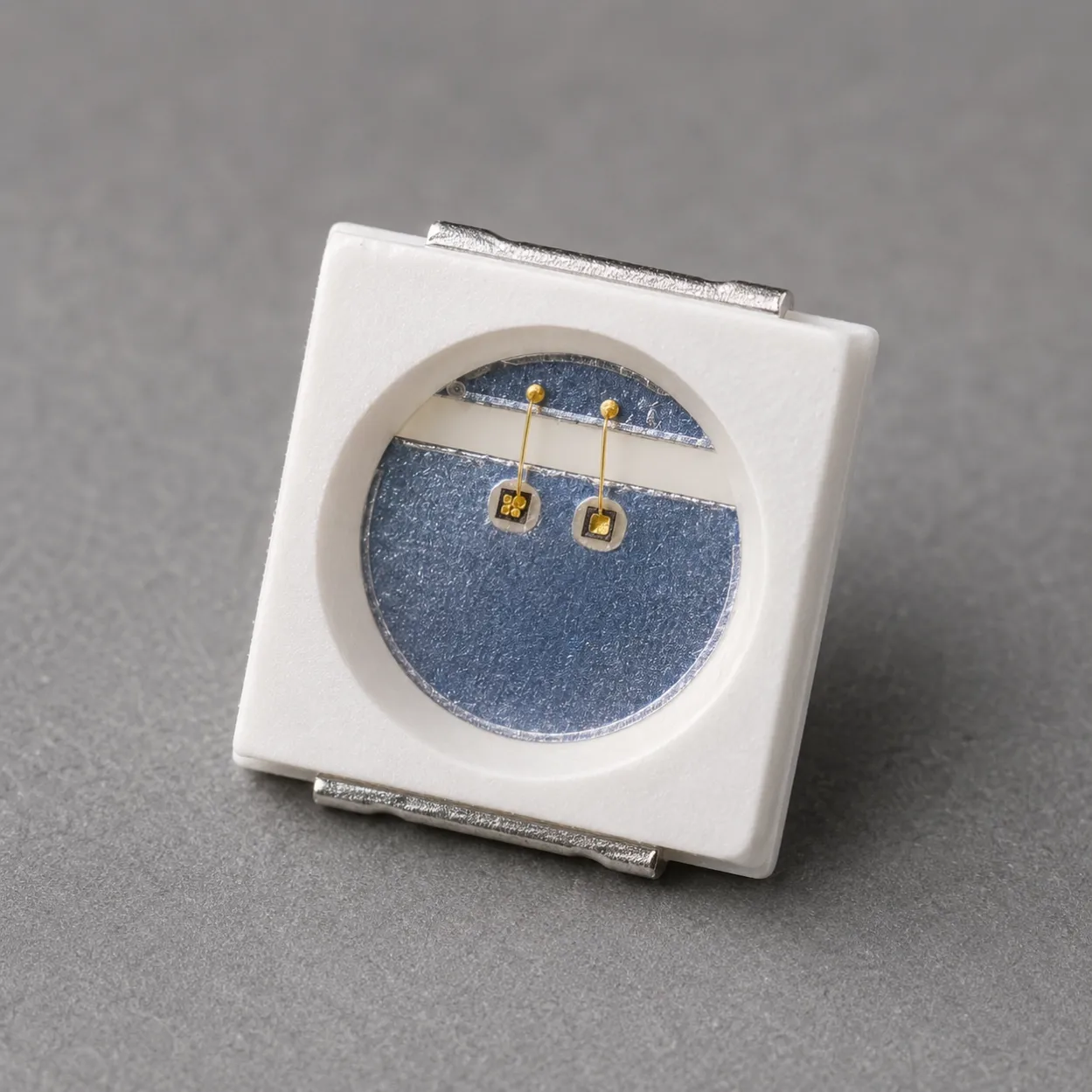
905nm multi-junction VCSEL SMD series with 5W 3030 and 70W 3535 packages for pulsed optical source evaluation, PCB integration and OEM development.
Specifications
- Product Type
- Multi-Junction VCSEL SMD Series
- Wavelength
- 905nm typ.
- Optical Output Power
- 4W min. / 5W typ.; 60W min. / 70W typ.
- Transverse Mode
- Multi-mode VCSEL
- Operating Mode
- Pulse; 100ns (5W) / 5ns (70W), 0.1% duty cycle
- Beam Divergence
- 20° D86 / 18° D86
- SMD Package Options
- 3030 / 3535
1. 905nm Multi Junction VCSEL SMD Series for Pulsed PCB Integration
The 905nm Multi Junction VCSEL SMD Series provides two fixed surface-mount configurations for pulsed near-infrared optical-source development, SMT assembly and PCB-level integration: a 5W 3030 model and a 70W 3535 model.
These are separate package, driver and test-condition configurations, not endpoints of a continuous 5W-to-70W power range. Both are specified at 905nm typical wavelength, but their optical output, forward current, pulse width, die format and package size require independent engineering evaluation.
The series is intended for component-level development of pulsed 905nm transmitters used in rangefinding, distance measurement, industrial sensing and OEM optical modules. Final module performance depends on the complete driver, PCB, optics, receiver, thermal path and system-level safety evaluation.
Typical customer and development directions include:
- Pulsed 905nm optical-source evaluation
- Laser rangefinding and distance-measurement development
- Industrial sensing and object-detection equipment
- PCB-mounted near-infrared transmitters
- SMD assembly and production-process evaluation
- OEM optoelectronic module development
Lead Time: In-stock products are dispatched within 3 business days; custom-packaged products have a lead time of 15–20 days.
MOQ: The minimum order quantity is 1 reel; selected special models support small-batch orders.
2. 5W 3030 and 70W 3535 Model Selection
The two products should be selected as distinct electrical and optical configurations. Confirm the applicable minimum, typical and maximum values, package drawing and test condition in the corresponding datasheet before design qualification.
Parameter | 905nm 5W 3030 VCSEL SMD | 905nm 70W 3535 VCSEL SMD |
|---|---|---|
Package format | 3030 SMD | 3535 SMD |
Chip specification | 8mil x 8mil | 18mil x 15mil |
Optical output power | 4W min.; 5W typ.; 5W max. | 60W min.; 70W typ. |
Forward current | 1A | 15A |
Forward voltage | 20V typ. | 20V typ. |
Wavelength | 899nm min.; 905nm typ.; 911nm max. | 895nm min.; 905nm typ.; 915nm max. |
Beam divergence | 20° D86 | 18° D86 |
Specified test condition | 25 °C, 100ns pulse width, 0.1% duty cycle | 25 °C, 5ns pulse width, 0.1% duty cycle |
The 905nm 5W 3030 Multi-Junction VCSEL SMD is the compact option for projects whose PCB area and driver capability align with its specified 1A, 100ns pulse condition.
The 905nm 70W 3535 Multi-Junction VCSEL SMD is the higher-peak-output option for designs able to support the specified 15A, 5ns pulse condition. The two devices are not electrically interchangeable and should not share a driver design without module-level validation.
3. PCB Integration and SMD Package Direction
Both products are supplied as surface-mount VCSEL components for PCB integration and tape-and-reel production handling. Each corresponding datasheet states a loading quantity of 4,000 pieces per reel. The package and die format differ, so land pattern, polarity, soldering process, optical clearance and board-level current path must be evaluated for the selected model.
For either configuration, verify pulse-driver voltage compliance, peak-current control, pulse shape, rise and fall time, parasitic inductance, repetition rate, duty cycle and the actual electrical and thermal path in the intended PCB and optical assembly.
Choose this SMD Series when the project requires a completed surface-mount component for direct PCB placement. Customers requiring die attach, wire bonding, submount assembly or custom package development can instead review the 905nm Multi Junction VCSEL Bare Die Series.
Related Articles
4. Application Development, Evaluation and Documentation Support
The 905nm VCSEL SMD Series supports component-level pulsed optical sources in rangefinding, distance measurement, industrial sensing and application-specific OEM transmitter modules. The output value in the datasheet applies only under the stated test condition and does not establish finished-device range, eye-safety classification, regulatory approval or performance in a particular end product.
For related application planning, review the Sensing & Machine Vision solution. Evaluation can address package selection, PCB layout, pulsed-driver behavior, reflow-process development, optical alignment and initial module integration. An Evaluation Kit with 10 pcs / KIT is available for PCB-layout verification, driver testing, pulse-control evaluation, soldering-process development, optical alignment and initial system integration.
Samples & Pilot Production: Evaluation kits, low-volume pilot production, and pre-production validation are supported.
Project-specific evaluation can include:
- 5W 3030 or 70W 3535 configuration selection
- Peak-current and pulse-control evaluation
- PCB pad, package polarity and reflow review
- Board-level electrical and thermal-path assessment
- Lens, window and optical-alignment review
- Evaluation quantity and supply planning
For component-level project evaluation, an Initial Product Report covering the Laser Diode Series and VCSEL Laser Diode Chip Series has been filed with the U.S. FDA CDRH. This filing supports technical documentation and product evaluation.
For applicable products, CE, EMC, EN 60825, LVD, RoHS, REACH and halogen-free certification and compliance documents are available. Documentation depends on the corresponding product model and does not represent certification of the customer's finished device.
5. Frequently Asked Questions
FAQ 1. Which 905nm VCSEL SMD model should I select: 5W 3030 or 70W 3535?
Start with the required peak optical output, available PCB area and the pulse-driver condition your design can validate. The 5W 3030 product is specified at 1A with a 100ns pulse width, while the 70W 3535 product is specified at 15A with a 5ns pulse width. Select each as its own package-and-driver configuration, not as an interchangeable power setting.
FAQ 2. Are the 5W 3030 and 70W 3535 905nm VCSEL SMDs electrically interchangeable?
No. Their package format, die specification, forward current, specified pulse width, wavelength limits and beam-divergence values differ. A PCB, driver and optical assembly must be evaluated against the datasheet and the intended operating condition for the selected model.
FAQ 3. What should be checked when integrating a 905nm VCSEL SMD onto a PCB?
Confirm the applicable land pattern, polarity, soldering and reflow conditions, current path, driver voltage compliance, pulse shape, parasitic inductance, local heat flow and optical clearance. The finished module should then be evaluated for actual pulse current, optical output, package alignment, downstream optics and production repeatability.