
Sep 19, 2026Technical Insights
How Do You Choose a Light Source for a Rubidium Atomic Clock?
How to choose a rubidium atomic clock light source: 795nm D1 matching, temperature tuning, single mode behaviour, linewidth, 3.417GHz modulation and aging.
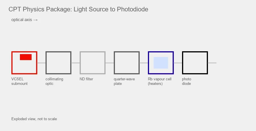
Key takeaways
- Wavelength is the entry ticket, not the specification. What matters is whether the part lands on the D1 feature at the physics package’s real operating temperature — which is why the 0.06nm/°C tuning arithmetic decides your bin, your yield and your thermal design.
- You need optical sidebands, not an electrical bandwidth number. Published implementations span a very wide RF-drive range, and RF-to-sideband conversion efficiency varies enough between devices to be a selection criterion.
- The cell usually needs controlled microwatt-level power, not maximum available laser output. NIST’s CSAC requirement list specifies 50 μW to 1 mW output; published systems run tens to hundreds of μW at the cell.
- Aging is a clock specification. Wavelength, power and polarization drift over life become light shift, and light shift becomes frequency drift.
For a rubidium atomic clock, the first question is not “Which 795nm laser should I buy?”
The first question is “Which rubidium clock architecture am I building?”
Rubidium frequency standards include lamp-pumped systems, laser-pumped microwave clocks, pulsed optical pumping designs and coherent population trapping (CPT) systems. Some work on the rubidium D2 transition near 780nm. Many compact CPT designs use the rubidium D1 transition near 795nm because it can provide favourable resonance contrast in common compact configurations.
This article focuses on that common 795nm D1 light source problem, especially for compact Rb-87 CPT systems. In that architecture, wavelength is only the first requirement. A useful source must also provide suitable single-mode behaviour, linewidth, polarization, optical power, tuning range and radio-frequency modulation performance at the operating temperature of the clock.
The specification at a glance
A starting framework, not a universal requirement list. Every value must be re-derived from your own clock architecture.
Parameter | What a compact Rb-87 D1 CPT design typically needs | Why it matters |
|---|---|---|
Centre wavelength | Rb-87 D1 near 794.979nm in vacuum, usually written 795nm | Must reach the D1 absorption structure |
Wavelength at operating point | On the D1 feature at package temperature, not at 25 °C | Datasheet test conditions rarely match the clock |
Temperature tuning | ~0.06nm/°C typical for a single-mode VCSEL | Sets how tight the incoming bin must be |
Operating temperature | Elevated; NIST cites 75 °C ± 5 °C as representative | Chosen to tune onto the line |
Mode behaviour | Single longitudinal, transverse and polarization mode | Unwanted modes interact differently with the vapour |
Linewidth | Below 100 MHz in NIST’s CSAC requirement list | Contributes to FM-to-AM noise and clock instability |
Modulation and RF drive | Generates the CPT resonance; sets sideband-to-carrier distribution | |
Optical output | 50 μW to 1 mW in NIST’s CSAC requirement list | Too much causes power broadening and light shift |
Polarization | Stable linear output, defined axis, high PER | External wave plates set the final polarization state |
Aging | Wavelength, power and polarization drift over life | Becomes clock frequency drift |
Why 795nm appears in so many rubidium clock designs
The Rb-87 D1 transition connects the 5S½ ground state to the 5P½ excited state, at approximately 794.979nm in vacuum. In engineering specifications it is normally shortened to 795nm.
A precision trap: vacuum versus air wavelength
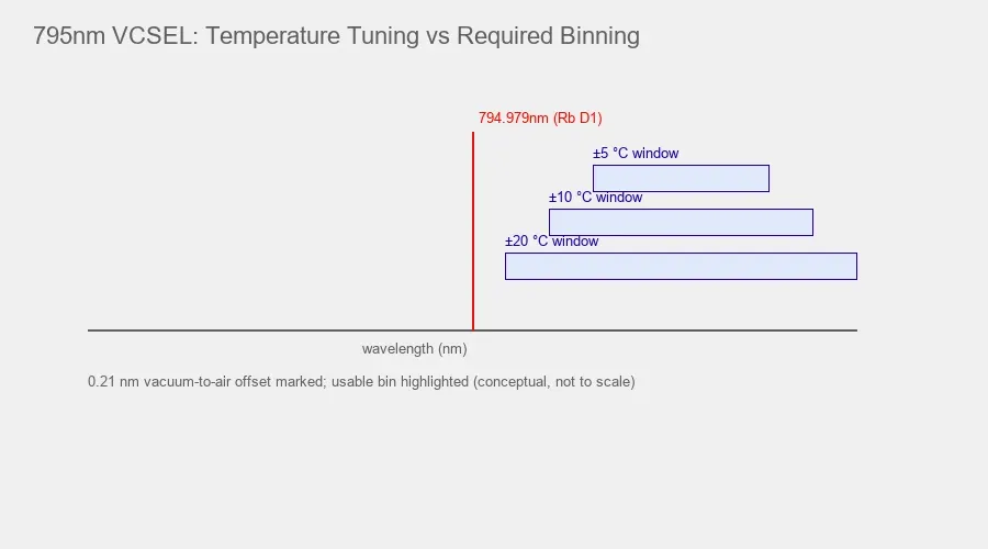
Some datasheets quote wavelength in air, others in vacuum. For the Rb-87 D1 line the difference is about 0.21nm — equivalent to roughly 3.5 °C of VCSEL temperature tuning at 0.06nm/°C. That is large enough to matter in a tightly binned clock source, and large enough to make a perfectly good part look out of specification.
Always state the wavelength convention when comparing parts or writing a bin specification.
Why D1 rather than D2
The same atom has a D2 transition near 780nm, and 780nm systems exist. The reason 795nm dominates compact CPT clocks is contrast. One influential NIST CSAC development illustrates why D1 became attractive: its first CSAC physics package used the Cs D2 line and reported a CPT resonance contrast of 0.9% with a short-term instability of 6 × 10⁻¹⁰/√τ, while the subsequent Rb-87 D1 package reported 4.6% contrast and 4 × 10⁻¹¹/√τ — roughly an order of magnitude better short-term stability, attributed to the higher D1 contrast and Rb-87’s fewer Zeeman sublevels. This is a single, informative example rather than a controlled D1-versus-D2 experiment, since the atomic species changed as well.
Contrast matters because the clock needs a strong, narrow atomic discriminator to lock an electronic oscillator. Note the trade-off in the other direction: Rb has a lower vapour pressure than Cs, so a Rb cell needs a higher temperature to reach comparable absorption — a heater-power cost in a SWaP-constrained design.
Choose the laser wavelength from the atomic transition and interrogation architecture first. Do not select a source simply because it is sold as an atomic clock laser.
The clock still measures a microwave transition
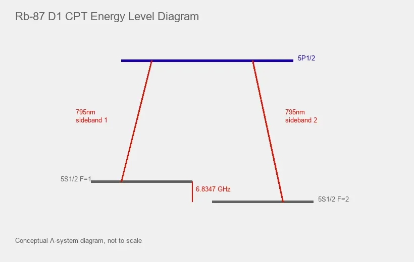
The optical wavelength is near 795nm, but the clock frequency comes from the ground-state hyperfine splitting of Rb-87. NIST lists the unperturbed value as:
In a common CPT implementation, the laser is directly modulated at approximately half this frequency so the first-order optical sidebands are separated by the full hyperfine splitting:
≈ 3.417 GHz
The two sidebands then address transitions from the two ground-state hyperfine levels to a common excited state, creating the CPT resonance used as the clock discriminator.
This is why the source needs more than a correct centre wavelength — it must also respond usefully to GHz-range modulation. Other CPT schemes use different modulation arrangements, sideband orders or external modulators, so the exact RF requirement must come from your architecture rather than a generic “Rb atomic clock” label.
Start with wavelength at the real operating temperature
A datasheet that says 795nm at one test condition does not guarantee the laser will sit on the required Rb transition in the finished clock. Semiconductor laser wavelength changes with both temperature and drive current, and for a VCSEL the temperature coefficient dominates.
The arithmetic that decides your bin specification
Two independent sources converge on the same figure: Sandia’s VCSEL characterisation for atomic sensors gives a typical tuning coefficient of 0.06nm/°C, and NIST’s CSAC review quotes VCSEL frequency tuning of roughly 30 GHz/K, which at 795nm works out to 0.063nm/K.
Work the consequence through:
Temperature adjustment available in the package | Wavelength range you can cover | Required accuracy of the incoming part |
|---|---|---|
± 5 °C | ± 0.30nm | Within ± 0.30nm at the reference condition |
± 10 °C | ± 0.60nm | Within ± 0.60nm |
± 20 °C | ± 1.20nm | Within ± 1.20nm |
This is the single most useful calculation in the selection process, and it explains three things at once:
Why clock VCSELs run hot. If the wavelength must tune up onto the D1 line, an elevated setpoint is a design choice rather than a thermal compromise. NIST’s summary of CSAC VCSEL requirements cites 75 °C ± 5 °C as a representative example, and cell temperatures around 90 °C are typical for Rb in a 20 kPa nitrogen buffer gas cell.
Why wavelength binning is not optional at volume. With a narrow temperature budget, an unbinned wafer distribution produces a low yield of usable parts.
Why “795nm ± 1nm” on a datasheet may be unusable. A ±1nm distribution needs roughly ±17 °C of tuning authority to guarantee coverage — more than most compact physics packages have.
What to request from the supplier
Centre wavelength at a defined current and temperature with the convention stated; tuning coefficients versus temperature and versus current; recommended and maximum operating temperature range; mode behaviour across the full tuning range, including where any mode hops or polarization switches occur; and the unit-to-unit wavelength distribution with available bins.
The key question is not whether the room-temperature wavelength is close to 795nm. It is whether the device can be placed on the desired D1 feature and held there at the temperature where the physics package actually operates, with margin left for control-loop authority and end-of-life drift.
Single-mode behaviour protects the optical interaction
Atomic spectroscopy is sensitive to spectral structure. A nominally correct wavelength is less useful if significant power appears in unwanted optical modes that interact differently with the vapour cell.
NIST’s CSAC requirement list is blunt about this: single longitudinal, transverse and polarization mode. All three, not just the first.
Read “single mode” carefully — a datasheet may describe transverse mode behaviour, spectral side-mode suppression, or both, and a part can be single transverse mode while still misbehaving at the edges of its current range. Ask for SMSR with its measurement condition, the optical spectrum across the full current and temperature range, and a mode-hop map showing where in that plane hops occur.
A high SMSR confirms the desired mode dominates, but it must be checked under the same temperature, drive and modulation conditions the clock will use — applying several GHz of RF changes the picture.
Linewidth matters because the atomic resonance is the reference
Published benchmarks
Reference points from the literature, not requirements:
Source | Reported linewidth | Context |
|---|---|---|
Typical commercial VCSEL (NIST review) | ~50 MHz | General availability at the time of writing; 3 MHz devices had been reported |
NIST CSAC VCSEL requirement | < 100 MHz | Specification target for chip-scale clocks |
795nm single-mode VCSEL | ~100 ± 20 MHz, heterodyne beat-note | Rb-87 lin‖lin CPT experiment, modulated at 3.417 GHz |
Custom 894.6nm VCSEL for Cs CPT | Consistent with measured frequency noise and ~1 × 10⁻⁸ Allan deviation at 1 s | |
Micro external-cavity diode laser, 795nm | Sub-MHz, package under 1 cm³ | Miniature Rb clock with short-term stability around 3.7 × 10⁻¹¹ at 1 s |
Note the spread: two orders of magnitude between a conventional clock VCSEL and an ECDL-class source. Both have been demonstrated in working clock systems.
Why it is not a parameter to ignore
Compact CPT clocks tolerate tens-of-MHz VCSEL linewidths because the CPT resonance depends on the relative phase stability between the two light fields — the microwave phase — rather than the absolute stability of each, and because the buffer gas broadens the optical transitions anyway.
But a broad linewidth still degrades performance through FM-to-AM noise conversion in the atoms, a documented contributor to CPT clock instability. Recent compact ECDL work has demonstrated sub-MHz linewidths while retaining GHz modulation bandwidth, showing that narrower sources raise the performance ceiling when the system can accept a different architecture.
Insist on a measurement definition
“Linewidth” is quoted in at least three incompatible ways: Lorentzian FWHM from a heterodyne beat note, a value derived from an integrated frequency-noise spectrum, and a number implied by an instrument-limited spectrum-analyser trace. Two suppliers can quote figures differing by 5× and both be honest. Ask for the method, the integration bandwidth and the operating point.
The source architecture trade-off
Source direction | Typical reason to consider it | Main trade-off |
|---|---|---|
VCSEL | Very compact, low power, direct GHz modulation, circular beam, low threshold | Linewidth and spectral noise may limit the highest performance |
DFB or similar edge-emitter | Potentially narrower spectral behaviour depending on design | Modulation architecture, beam shaping and package size need review |
External cavity diode laser, including chip-scale ECDL | Much narrower linewidth, strong spectroscopy performance | Larger and more complex — though chip-scale versions are eroding this gap |
Discharge lamp | Established in traditional rubidium standards | Broad optical spectrum, high power draw; not a route for compact CPT |
Do not write “the laser must be below 100 MHz” as a universal rule. Derive the target from required clock stability, cell linewidth, interrogation scheme and SWaP budget.
RF modulation must produce sidebands, not just bandwidth
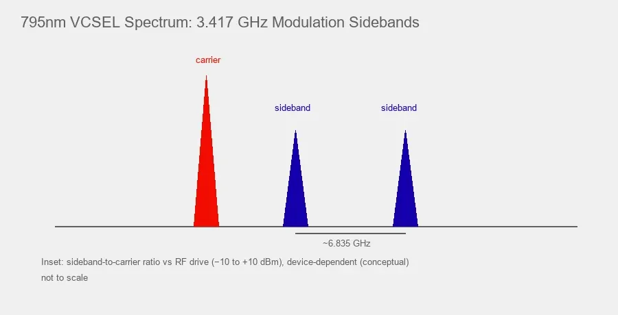
For a common Rb-87 CPT scheme using symmetric first-order sidebands, the source must respond usefully around 3.417 GHz. A datasheet may list a modulation bandwidth, but the clock does not care about a 3 dB electrical number. It needs optical sidebands with the required amplitude and phase behaviour.
The published range is very wide
Published implementations span a wide RF-drive range. NIST’s CSAC work reports that for some VCSELs, under −6 dBm at 3.4 GHz is sufficient to transfer around 60% of the optical power into the desired first-order sidebands, and gives −6 dBm at 3.4 GHz (or 0 dBm at 4.6 GHz for Cs) as the requirement for reaching a phase modulation index above 1.8. By contrast, a published Rb-87 lin‖lin CPT experiment drove a 795nm VCSEL at 3.417 GHz with +10 dBm.
That is roughly a factor of 40 in RF power between two working implementations. The required drive depends strongly on the specific VCSEL, the impedance match and the target modulation index — which makes conversion efficiency a genuine selection criterion, since RF drive sits inside the SWaP budget. For context, NIST reports demonstrated 3.417 GHz local oscillators for Rb consuming around 2.1 mW of DC power.
Modulation index is also a light-shift control
In some CPT configurations, an operating modulation index can be found where the combined light shift from the carrier and sidebands approaches zero, and some designs add a servo that locks RF power to that point. Modulation index is therefore not only a signal-amplitude parameter — it is one of the main handles on long-term frequency stability.
What to measure or request
Frequency modulation response at the exact intended RF frequency rather than a rounded value; sideband-to-carrier power distribution versus drive level; achievable modulation index at a given drive power; residual amplitude modulation; modulation response versus bias current and versus temperature; impedance match and any required matching network; and stability of the sideband spectrum over time.
If the datasheet says “3.4 GHz modulation support” and your architecture requires 3.417 GHz, test at the exact operating frequency with margin. A recent compact Rb CPT clock using a directly modulated chip-external-cavity diode laser reported a 4 GHz 3 dB bandwidth specifically to cover the ~3.4 GHz requirement with headroom.
Verify the optical modulation result, not only the electrical input specification.
Optical power should be controllable, not maximised
Atomic clock light sources are not selected by maximum optical power. The vapour cell only needs enough resonant optical power to create a useful signal with acceptable signal-to-noise ratio. More power introduces power broadening and light shifts, and the optimum depends on beam size, cell composition, buffer gas, temperature, polarization and interrogation sequence.
The scale is worth internalising. NIST’s CSAC VCSEL requirement list specifies optical output power of 50 μW to 1 mW. Published CPT examples span tens to hundreds of microwatts at the cell — characterisation work at 700 μW, physics packages near 188 μW, vapour-cell experiments under 60 μW. Chip-scale optics packages commonly include a neutral density filter specifically to attenuate the beam down to roughly 10 μW at the cell.
A component datasheet quoting 0.13 mW typical output is therefore not an underpowered part for this application. It sits inside the expected range once coupling and attenuation are accounted for.
Ask instead about optical output at the intended bias current and operating temperature, power stability after warm-up, relative intensity noise at the Fourier frequencies your servo cares about, output versus temperature, beam divergence and coupling efficiency into your optical path, and the ability to attenuate or control power reproducibly.
A source with excessive minimum power can be as inconvenient as one with insufficient output, because the system then needs fixed attenuation — adding components, thermal load and light-shift sensitivity.
Polarization is part of the atomic interaction
CPT resonance strength depends on how the optical field couples the atomic states. Many compact designs create circular polarization with a quarter-wave plate after the laser, which only works cleanly if the incoming light is a stable single linear polarization. Source polarization stability is a system requirement even though the final state is set by external optics.
This is a known VCSEL failure mode, not a theoretical concern. The vertical cavity design allows two orthogonal polarization modes to be resonant; they can differ in frequency by many gigahertz, and the output can flip between them. Polarization jumps still occur in single-mode VCSELs, and mode competition between polarizations causes amplitude noise — which becomes intensity noise on the photodiode as soon as a polarizer is in the path. Monolithic surface gratings and other polarization-stabilising structures exist specifically to address this.
Review polarization extinction ratio, the orientation and tolerance of the dominant axis, switching behaviour with both drive current and temperature, the effect of package and die-attach stress, and stability under RF modulation.
A device meeting wavelength and linewidth requirements but switching polarization unpredictably will still produce an unstable clock signal. This is why the bare die, submount and package should be treated as part of the optical source system rather than as mechanical choices.
Temperature control is an optical requirement
Temperature control is not only for laser lifetime. It is wavelength control, which is why it belongs in the optical specification rather than the mechanical one.
Evaluate setpoint resolution and stability, warm-up time to optical steady state, heat coupling from the vapour cell (which itself runs hot), the ambient range and the control authority it demands, package thermal resistance from junction to control sensor, wavelength drift after warm-up, and the interaction between RF drive power and junction temperature.
That last point catches teams regularly: changing the modulation index during optimisation also changes the laser’s thermal state and therefore its wavelength lock point — the two loops interact.
A related failure mode is worth naming: when a gradient develops between the thermistor and the die, junction temperature changes even though the sensor reads correctly. The frequency servo pulls the laser back onto resonance by changing DC current, but output power and modulation index shift in the process, altering the light shift and moving the clock frequency. Several designs address this by deriving the temperature lock point from the atomic absorption signal itself rather than from a nearby sensor.
Measure the optical spectrum after the full physics package reaches steady state.
Aging, drift and lifetime are clock specifications
This is the area most commonly missing from a source evaluation, and the one that most often decides whether a clock meets its long-term specification in the field.
As VCSELs age, their optical properties change. Published work surveying 795nm VCSELs for Rb-87 D1 examines exactly this — wavelength drift, power drift and polarization stability over time, framed against clock stability requirements. The mechanism is direct: a slow wavelength or power change moves the light-shift operating point, and light shift becomes clock frequency drift.
For context, commercial chip-scale atomic clocks specify long-term aging below 9 × 10⁻¹⁰ per month and short-term Allan deviation around 3 × 10⁻¹⁰ at τ = 1 s, in under 17 cc and under 120 mW total. The source is one contributor inside that budget.
Ask a supplier for life-test data at the actual elevated operating temperature rather than 25 °C; wavelength drift and optical power degradation per 1,000 hours at constant current; threshold current shift and polarization stability over life; failure-rate data (FIT or MTTF) with test conditions; whether the data comes from this exact die and process or an analogous product; and lot-to-lot consistency from epitaxy.
Be specific about the test temperature. Reliability data taken at room temperature says very little about a device that will spend years at 75–90 °C.
On sampling: same-lot samples are useful for controlled prototype comparisons, but production qualification should include multiple representative lots wherever possible, to expose lot-to-lot wavelength, power and polarization variation.
Designing back from the clock specification
Clock-level requirement | Source parameter it constrains |
|---|---|
Short-term Allan deviation (τ = 1 s) | Linewidth, RIN, FM noise, CPT contrast and resonance linewidth |
Medium-term stability | Light shift sensitivity — therefore power, wavelength and modulation index stability |
Long-term drift / aging | Source wavelength and power aging, polarization stability |
Temperature coefficient of the clock | Wavelength vs temperature, control loop authority, RF-thermal coupling |
Total power and volume budget | Laser bias + heater/TEC + RF drive; package format |
Cost at volume | Binning yield, which follows directly from the tuning arithmetic |
Working through this before writing an RFQ turns a vague “795nm VCSEL for atomic clock” request into a specification a supplier can engineer against.
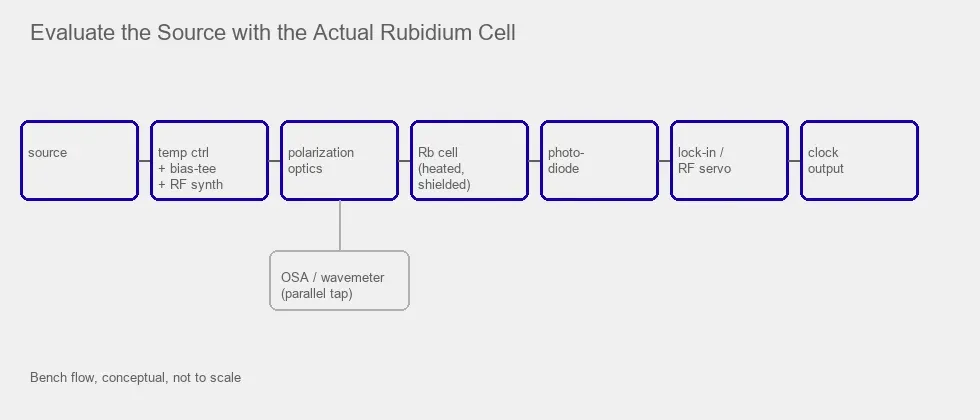
Evaluate the source with the actual rubidium cell
A spectrum analyser and a datasheet can reject unsuitable parts, but cannot fully qualify a source for a clock. The final test is the atomic system.
Step | What to confirm |
|---|---|
1. Free-running optical spectrum | Centre wavelength, linewidth, side modes and polarization at the intended temperature and current |
2. Scan the Rb D1 absorption structure | The required transition is reachable — and how much tuning margin remains at each end |
3. Apply the clock RF modulation | Sideband generation at the exact frequency and bias, and the RF power needed for the target sideband ratio |
4. Measure the CPT resonance | Contrast, linewidth, transmitted optical power, signal-to-noise ratio |
5. Optimise power and modulation index | Light shift mapped against both — the maximum of either is rarely the optimum |
6. Test thermal sensitivity | Wavelength lock point, CPT signal and clock output across the intended package and ambient range |
7. Measure stability | Allan deviation and drift on a working prototype, not a standalone laser spec |
8. Life-test the winning candidate | At real temperature, drive and RF conditions, long enough to extrapolate against your aging target |
How to read a 795nm VCSEL specification
1ONELASER lists a 795nm Single-mode VCSEL Bare Die for Rb Atomic Clock with the following published component-level values:
Parameter | Published value | The question it raises |
|---|---|---|
Wavelength | 795nm typical, 794.5nm – 795.5nm | Vacuum or air? At what reference temperature and current? |
Optical output | 0.13 mW typical at the stated condition | Inside the 50 μW–1 mW range NIST specifies — confirm at your bias point and temperature |
SMSR | ≥ 30 dB | Measured at which current and temperature, and does it hold under RF drive? |
PER | ≥ 15 dB | Is the axis orientation specified and stable across temperature? |
Spectral linewidth | ≤ 100 MHz | By which measurement method and integration bandwidth? |
FM modulation bandwidth | ≥ 3.4 GHz | What sideband-to-carrier ratio at 3.417 GHz, and at what RF power? |
Beam divergence | 17° typical at 1/e² | What coupling efficiency does that give in your optical path? |
Note the wavelength spread implied: a ±0.5nm window needs roughly ±8 °C of tuning authority at 0.06nm/°C. If your physics package cannot provide that, you need a tighter bin — a commercial conversation to have upfront, not after samples arrive.
Convert every line of an atomic clock laser datasheet into a bench test tied to the actual physics package.
Sourcing reality, and what to send a supplier
Two constraints shape 795nm projects in a way they do not shape 850nm or 940nm ones. The supply base is narrower and production volumes are much smaller than mainstream 850nm or 940nm VCSEL markets — 795nm single-mode VCSELs serve atomic clocks, magnetometers and quantum sensing, with no consumer-scale volume underwriting the process, and NIST’s review notes that chip-scale clock yields demand epitaxial accuracy and uniformity beyond what typical semiconductor fabrication achieves. Binning is the commercial lever — because the tuning arithmetic is unforgiving, the useful conversation is about wavelength bins, reference conditions and screening rather than headline specifications. Agree the bin definition, measurement condition and acceptance criteria before the first order, and confirm the supplier can hold that bin across lots.
A request for quotation should therefore contain:
Requirement | Information to provide |
|---|---|
Atom, transition and architecture | Rb-87 D1 near 795nm or another line; CPT, pulsed optical pumping, laser-pumped or other |
RF modulation | Required frequency, sideband arrangement, target sideband ratio, and your available drive power in dBm |
Spectral requirements | Linewidth target with measurement definition; single longitudinal / transverse / polarization mode; minimum SMSR and test conditions |
Polarization | Required PER, axis orientation and stability across temperature |
Optical power | Target range at the cell, plus your coupling losses |
Temperature | Laser setpoint, physics package temperature, and tuning range available in your design |
Wavelength convention and bin | Vacuum or air; acceptable window at your stated reference condition |
Aging target | Acceptable wavelength and power drift per 1,000 hours |
Package and volume | Bare die, TO can or custom submount; sample / validation / production stage with forecast |
Final engineering rule
A 795nm label is necessary for a common rubidium D1 clock, but it is not sufficient.
The source must reach the required D1 feature at the actual operating temperature, stay in the desired longitudinal, transverse and polarization mode, provide an acceptable linewidth, generate the required RF sidebands at a realistic drive power, operate at an optical power that produces a stable atomic resonance rather than broadening and light shift — and hold all of that over years at elevated temperature.
VCSELs dominate compact CPT clocks because they combine small size, low power, a circular beam and direct high-frequency modulation. Narrower-linewidth diode or external-cavity sources become attractive when a design prioritises stability over minimum SWaP, and chip-scale ECDLs are eroding the size penalty that once made that choice obvious.
The correct choice is the source that produces the best atomic discriminator inside the complete clock architecture — not the one with the narrowest linewidth, highest power or most precise nominal wavelength on its datasheet.
Frequently Asked Questions
Why do many rubidium atomic clocks use light near 795nm?
795nm corresponds to the Rb-87 D1 transition from 5S½ to 5P½, at approximately 794.979nm in vacuum. Many compact Rb-87 CPT clocks use the D1 transition because D1-based configurations can provide favourable CPT resonance contrast. One influential NIST development reported 4.6% contrast for its Rb-87 D1 package, compared with 0.9% for an earlier Cs D2 package, although this was not a controlled D1-versus-D2 comparison. Other rubidium architectures use different transitions, including D2 near 780nm.
What temperature does a 795nm VCSEL for a rubidium clock run at, and how tight must binning be?
Elevated setpoints are common in chip-scale designs, because the wavelength is temperature-tuned onto the D1 line — NIST’s summary of CSAC VCSEL requirements cites 75 °C ± 5 °C as a representative example, with Rb cell temperatures around 90 °C. Binning follows directly from the tuning authority available: at roughly 0.06nm/°C, ±5 °C covers about ±0.3nm and ±10 °C about ±0.6nm. Work out your package’s control range first, then specify the bin. A wide bin with a narrow thermal budget produces poor yield.
How much RF power is needed to drive a 795nm VCSEL for CPT?
The published range is very wide. NIST reports that under −6 dBm at 3.4 GHz can transfer around 60% of optical power into the first-order sidebands for some VCSELs, while a published Rb-87 lin‖lin CPT experiment used +10 dBm at 3.417 GHz — roughly a factor of 40 apart. The requirement depends strongly on the device, the impedance match and the target modulation index, so it must be measured rather than assumed.
Does a 795nm rubidium clock laser have to be single mode?
For compact CPT architectures such as the NIST CSAC approach, single longitudinal, transverse and polarization mode behaviour is a key requirement — and in more than one sense, since NIST’s CSAC requirement list specifies all three. Unwanted modes interact differently with the vapour cell and reduce the quality or repeatability of the atomic signal. It is not a universal requirement across every rubidium clock architecture, so the required SMSR and spectral behaviour should be defined by the architecture and verified under modulation.
What linewidth is required for a rubidium atomic clock?
There is no universal limit. NIST’s CSAC requirement list specifies below 100 MHz; published systems have used VCSELs from roughly 20 MHz to around 100 MHz, while chip-scale ECDLs reach sub-MHz. The correct target depends on cell broadening, stability requirements, noise, SWaP and modulation architecture — and any quoted number is only comparable if the measurement method is stated.
How much optical power should reach the vapour cell?
NIST’s CSAC VCSEL requirement list specifies 50 μW to 1 mW output, and published systems run tens to hundreds of microwatts at the cell, often with a neutral density filter attenuating further. More is not better: excess power causes power broadening and light shift.
Is VCSEL the only light source option for a rubidium atomic clock?
No. Traditional clocks use discharge lamps, and laser-based systems use VCSELs, DFB-type lasers and external-cavity diode lasers. VCSELs suit compact CPT systems because of size, power consumption and direct high-frequency modulation. Chip-scale ECDLs have demonstrated miniature Rb clocks with sub-MHz linewidth sources in packages under 1 cm³.
How do I specify VCSEL aging for an atomic clock?
Ask for life-test data at the real elevated operating temperature, expressed as wavelength drift and optical power degradation per 1,000 hours, plus threshold shift and polarization stability over life. Room-temperature data is not a substitute. Tie the acceptable drift back to your clock’s long-term aging specification, since source wavelength and power drift become light-shift-driven frequency drift.