
Aug 13, 2026Technical Insights
How to Read a VCSEL Datasheet
How to read a VCSEL datasheet: what wavelength, optical power, beam divergence, linewidth, and threshold current mean for your device.
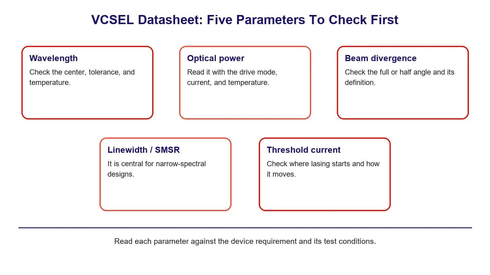
A VCSEL datasheet lists more numbers than most designs need, so the way to read one is to start from what your device requires and check those parameters first: wavelength, optical power, beam divergence, linewidth, and threshold current. 1ONEVCSEL publishes datasheets and test data for its chips, and this guide explains what each parameter means and what it implies for your device. It also flags which specifications depend on the package rather than the die.
Read the datasheet against your device, not top to bottom
A datasheet is written to describe the part, not to match your design, so reading it front to back buries the few parameters that decide whether the chip fits. Start from your requirement. Fix the wavelength, the power, the beam, and the drive conditions your device needs, then look up those lines first and treat the rest as supporting detail.
The parameters below are the ones that usually decide the fit. Each means something specific, and each implies something about the device you are building.
Wavelength: the center, the tolerance, and the temperature it is quoted at
The wavelength line has three parts worth reading together: the center wavelength, the tolerance around it, and the temperature the value is quoted at. The center is the nominal peak, the tolerance is how far a given part can sit from it, and the quoted temperature matters because the peak shifts with junction temperature and drive current.
The wavelength tolerance defines the allowable range for an individual part under the stated test conditions. It does not, by itself, tell you how tightly a production lot is distributed inside that range, which is a separate question covered in a guide on production consistency. The quoted temperature establishes the reference condition for the wavelength specification; to estimate how far the peak wavelength will shift in operation, look for a wavelength temperature coefficient or wavelength-versus-temperature data. A nominal wavelength alone, without tolerance or stated test conditions, is not sufficient for tight wavelength qualification. Which wavelength to choose in the first place is covered in a guide on VCSEL wavelength selection.
Optical power: read it with its drive conditions
Optical power is the parameter most often misread, because an optical-power figure is only meaningful when read together with its measurement conditions. Read it together with the drive mode, since the same part can be rated one way under continuous-wave operation and very differently under pulsed or quasi-continuous-wave (QCW) drive, and together with the drive current and temperature. For pulsed or QCW operation, also check pulse width and duty cycle, since a peak-power figure without those conditions is not directly comparable with a continuous-wave rating.
Also check whether the figure is per emitter or for a full array, because the total array output may be much higher than the output of a single emitter. For your device, the number that matters is the power under the conditions you will actually run, not the headline maximum. How much power a design needs, and under what conditions, is covered separately.
Beam divergence: the angle and what it asks of your optics
Beam divergence describes the angular spread of the output, but the quoted value is only meaningful together with its definition. Check whether the datasheet uses a full angle or a half angle, and whether the width is defined at FWHM, 1/e², or another intensity level. VCSELs generally produce a symmetric, comparatively low-divergence beam, which is easier to collimate or couple than the elliptical output of many edge-emitting lasers.
For your device, divergence influences the beam-shaping optics required and the achievable coupling efficiency into a fiber, lens system, or target area. A wider divergence is not a fault, but it changes the optical design, so it belongs in the comparison alongside wavelength and power.
Linewidth and side-mode suppression: central for some designs, not all
Linewidth, sometimes given as spectral width, is the range of wavelengths the device emits at a set operating point, and side-mode suppression describes how well the main mode dominates any secondary ones. For many broadband illumination applications, these parameters may be secondary to wavelength, total optical power, and beam profile.
For a narrow-spectral application such as atomic sensing or spectroscopy, they become central, because the source has to sit on a narrow feature and stay single-mode. Because the requirement varies so much by application, these parameters are best matched through individualized screening rather than read as a single universal number.
Threshold current: where lasing starts, and why it moves
Threshold current is the current at which lasing begins. It is derived from the L-I curve using the method specified by the manufacturer or test procedure, rather than simply read from a single raw point. Above threshold, optical output typically increases approximately linearly over part of the operating range, with the slope described by slope efficiency.
For the driver designer, the important point is not threshold current in isolation, but where it sits relative to the intended operating current and how it shifts over temperature.
What a bare-die datasheet may not tell you
A bare-die datasheet characterizes the die itself, but it cannot fully describe the thermal, mechanical, and electrical behavior of the final packaged assembly. Some die suppliers do specify parameters such as ESD susceptibility or die-level thermal characteristics, but package-level thermal resistance, mechanical handling, parasitics, and assembly-dependent performance depend on the package and mounting configuration.
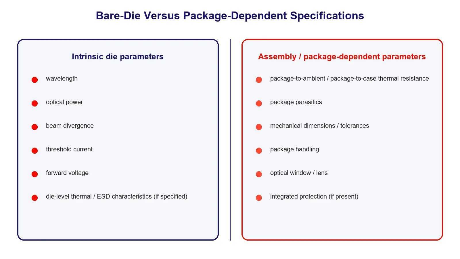
When comparing bare die with SMD, COB, or other packaged configurations, separate the intrinsic die parameters from the assembly-level specifications. Wavelength, optical power, divergence, threshold current, and die-level electrical limits describe the emitter itself; thermal resistance to the final heat sink, package parasitics, mechanical handling limits, and some protection characteristics depend on how the die is mounted and packaged. A datasheet also describes a specification, not the spread of a production lot.
About 1ONEVCSEL
1ONEVCSEL is the VCSEL product line of 1ONELASER. It supplies VCSEL components rather than finished devices: single emitters and arrays across 650 to 1064 nm, in selected bare-die, SMD, and COB configurations, with datasheets and test data to support evaluation.
A datasheet is best read alongside a small evaluation batch, so engineering samples and small evaluation batches are available, along with test data tied to the parts supplied. To match a datasheet to a design, the useful starting information is the target wavelength and tolerance, the required optical output and drive mode, the beam requirement, and the packaging format.
Frequently asked questions
What are the most important parameters on a VCSEL datasheet?
The parameters that usually decide fit are wavelength (with its tolerance and quoted temperature), optical power (with its drive conditions), beam divergence, linewidth or spectral width, and threshold current. Read those against your device first and treat the rest as supporting detail.
Why is optical power meaningless without conditions?
Because the same part can be rated very differently under continuous-wave, pulsed, or QCW drive, and per emitter versus per array. A power number is only comparable when you know the drive mode, drive current, temperature, and whether it applies to one emitter or a full array.
Which specifications depend on the package rather than the die?
A bare-die datasheet describes the die itself and may include die-level parameters such as ESD susceptibility and die thermal characteristics. Package-level specifications, such as thermal resistance to the final heat sink, package parasitics, mechanical handling limits, and some protection features, depend on how the die is mounted and packaged, so confirm those for the configuration you will use.
Does the wavelength on a datasheet change in use?
Yes. The center wavelength is quoted at a specific temperature, and the actual peak shifts with junction temperature and drive current. For precision applications this shift can be critical; for broad illumination applications it may be less important, depending on the allowable wavelength tolerance.
What is threshold current and why does it matter?
Threshold current marks the onset of lasing and helps define the relationship between the driver’s intended operating current and the laser’s usable operating range. Its temperature dependence also matters because the threshold can shift as operating conditions change.