
Sep 19, 2026Application Insights
How to Select and Arrange Light Sources for a Red Light Face Mask
How to select and arrange light sources for a red light face mask: wavelength, irradiance, dose, emitter pitch, uniformity, heat and LED vs VCSEL trade-offs.
Key takeaways
- Specify the optical field first, the emitter second. Target irradiance at the skin, treatment time, working distance, uniformity rule and thermal limit all come before a part number.
- Emitter count is a marketing number. Published commercial examples range from roughly 130 to 650 emitters, although counting methods differ, because brands count packages, dies and apertures differently.
- Published irradiance is not clustered. Published red-channel values in the examples below span at least 26 to 73 mW/cm², with reference devices in FDA comparison tables higher still.
- Irradiance and dose are not interchangeable. J/cm² = mW/cm² × s ÷ 1000, but the literature reports a biphasic response, so the same joule total at a different irradiance is not automatically equivalent.
- Uniformity is mostly geometry. Standoff and incidence angle vary continuously across a face, so two identical PCBs in two different shells produce two different irradiance maps.
A red light face mask should not be designed by choosing a wavelength first and then filling the PCB with as many emitters as possible.
The useful design sequence is the opposite. Define the intended optical dose at the skin, the treatment area, the acceptable nonuniformity, the emitter-to-skin distance and the thermal limit first. Then choose the wavelength, source type, optical power and emitter pitch that can produce that field across a three-dimensional face.
For most facial photobiomodulation products, LEDs remain the most common source because they are inexpensive, easy to distribute across a large area and available with broad emission patterns that overlap well at short working distances. VCSELs become useful when a design needs tighter wavelength control, a more directional beam, compact surface-mount integration or a deliberately controlled optical field. That does not make VCSEL the default choice for every mask.
The final result depends on the complete optical system, not on one component specification.
What the market actually publishes
Before defining your own specification, look at what finished masks declare. The useful lesson is not a target number — it is how wide the spread is.
Published example | Wavelengths | Declared irradiance | Emitter declaration |
|---|---|---|---|
633 ± 10nm red; 830 ± 10nm IR; 415 ± 10nm blue | Red 73 ± 5 mW/cm²; blue 64 ± 5 mW/cm²; red + IR 73 ± 5 / 55 ± 5 mW/cm² | 648 LEDs | |
Reference device cited in the same 510(k) comparison family | Red / IR | Listed at 125 mW/cm² in the comparison table | Not the basis of comparison |
HigherDOSE Red Light Face Mask (manufacturer-published) | 630nm red; 830nm NIR | Red 26 mW/cm²; NIR 24 mW/cm²; 50 mW/cm² combined | 66 dual-core LEDs, described as 132 diodes |
Red band ~620nm – 690nm; NIR band ~820nm – 880nm | Declared as a separate technical characteristic alongside energy dose | Not the basis of comparison |
Three observations matter. Published irradiance is not clustered — declared red-channel values differ by roughly a factor of three across the published examples, with reference devices in FDA comparison tables higher still, so there is no consensus figure to design toward. The figures are not directly comparable, because wavelength channels, measurement distance and geometry, sensor type and operating mode are almost never published alongside the number; two masks declaring “50 mW/cm²” may have measured entirely different things. Emitter counts are declared inconsistently, with brands counting packages, dies or illuminated apertures.
Use these values as orientation for where the category sits — not as design targets, and not as efficacy benchmarks.
Start with the treatment field rather than the emitter count
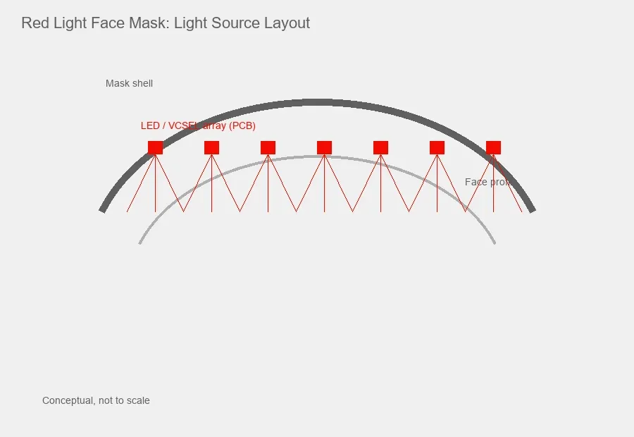
A face mask is an illumination system wrapped around a curved target.
The forehead, nose, cheeks, upper lip, jaw and chin do not sit at the same distance from the PCB. Even if every emitter produces identical optical power, the irradiance reaching those regions differs because distance and angle change continuously across the mask.
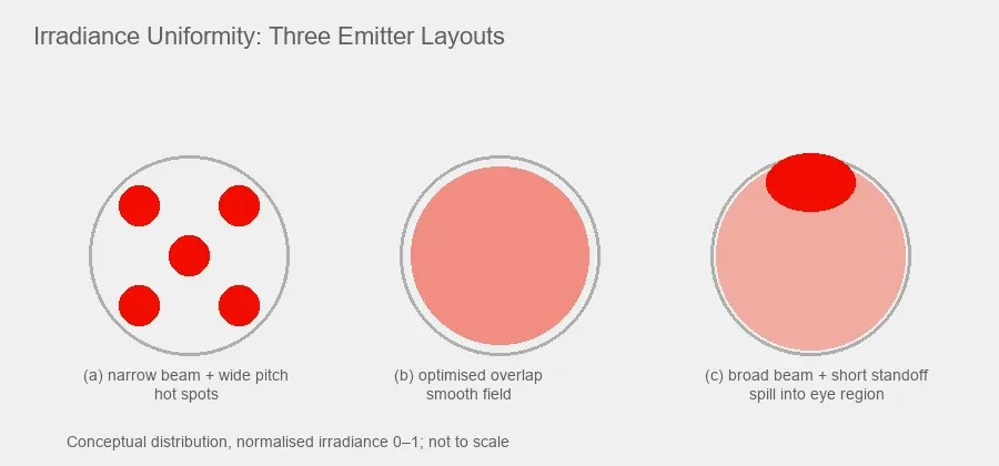
Two masks can use the same number of light sources and still produce very different optical fields. One may have a smooth irradiance distribution because neighbouring beams overlap at the skin. The other may create bright points directly below each emitter and low irradiance between them.
The first engineering target should therefore be a measured irradiance map at the intended skin surface.
For a new design, define at least:
Design input | What should be defined |
|---|---|
Treatment area | Full face or selected zones, with area in cm² |
Target irradiance | Measured at the skin plane, per channel |
Exposure time and radiant exposure | Session duration, and the J/cm² it implies |
Working distance | Emitter-to-skin distance by facial region: min / typical / max |
Uniformity criterion | An internal pass/fail rule for the irradiance map |
Thermal limit | Maximum component, enclosure and skin-facing temperature |
Eye region strategy | Optical exclusion, shielding, geometry or other safety controls |
Fix these before specifying a component. The full supplier-facing version of this list appears in the
checklist near the end of the article.
Why LED count is the most misleading number on the spec sheet
The category has a counting problem, and it directly affects sourcing decisions.
There are at least three different things a brand may be counting:
- LED packages — the number of discrete components placed on the board.
- Dies or chips — the number of emitting junctions. A single dual-core or multi-chip package contains two or more dies, which is how 66 packages become “132 diodes.”
- Apparent emission points — what the user sees illuminated, which may match neither of the above once a diffuser is fitted.
The market spread makes the problem concrete: one cleared mask declares 648 LEDs at 73 mW/cm² red, while another commercially published example declares 132 diodes at 26 mW/cm² red. Neither count predicts the other’s irradiance, because per-die power, pitch, beam angle and standoff all differ.
For an OEM specification, define emitter density as dies per cm² of treatment area, and state the package architecture separately. That is the number that interacts with beam angle, pitch and standoff. Total count on its own tells a supplier almost nothing.
Choose the wavelength from the intended optical protocol
Red light facial devices commonly use visible red wavelengths in the 630nm to 660nm region, sometimes combined with near-infrared wavelengths around 830nm to 850nm.
Published clinical work has used combinations such as 633nm and 830nm. Cleared devices declare either narrow tolerances (633 ± 10nm) or broader bands (620nm – 690nm red, 820nm – 880nm NIR). There is no single mandatory wavelength pair for every facial mask.
Band | Common nominal values | How it is generally positioned | Engineering consequence |
|---|---|---|---|
Red, shorter | 620nm – 635nm (630, 633nm) | Common in facial PBM literature and in surface-oriented and acne-oriented protocols, often paired with blue | Strong visible output, high perceived brightness, easy user feedback |
Red, longer | 650nm – 670nm (660nm) | Widely used across red-light PBM devices and skin studies, with incrementally different tissue propagation from shorter red wavelengths | Fully visible; spectral width matters if a declared band is narrow |
Near-infrared | 810nm – 860nm (830, 850nm) | Used where deeper tissue targets are intended | Invisible — no aversion response, so eye-safety analysis cannot rely on the user’s blink reflex |
Avoid two shortcuts: assuming 660nm beats 633nm because the number is larger, and assuming 850nm improves every mask. Penetration depth is not a fixed property of a wavelength — it depends on tissue type, power, distance and session parameters — so selection should follow the intended target and validation plan, not a depth ladder.
For an OEM project, specify a wavelength window and tolerance rather than a nominal value alone — for example 655nm ± 10nm peak, measured at 20mA and 25 °C junction — then re-measure under the conditions the finished mask will actually use, because peak wavelength shifts with junction temperature.
For additional wavelength planning, see Which VCSEL Wavelength Should You Choose and the Medical Beauty and Personal Care optical source platform.
Irradiance and dose must be considered together
Irradiance describes optical power delivered per unit area, usually in mW/cm². Radiant exposure — often called fluence or dose in photobiomodulation discussions — is usually expressed in J/cm².
For a constant irradiance:
Radiant exposure (J/cm²) = irradiance (mW/cm²) × exposure time (s) ÷ 1000
Irradiance at skin | Session time | Radiant exposure |
|---|---|---|
20 mW/cm² | 600 s (10 min) | 12 J/cm² |
30 mW/cm² | 600 s (10 min) | 18 J/cm² |
30 mW/cm² | 200 s (3 min 20 s) | 6 J/cm² |
73 mW/cm² | 180 s (3 min) | 13.1 J/cm² |
10 mW/cm² | 1,200 s (20 min) | 12 J/cm² |
That arithmetic is necessary, but it is not enough to define biological equivalence.
Photobiomodulation literature repeatedly reports a biphasic dose response. Too little optical exposure may not produce the intended response, while increasing irradiance or total exposure beyond an effective range does not necessarily produce a better result. Reviews also note that the same total J/cm² delivered with different irradiance and exposure time combinations can produce different outcomes.
Rows 1 and 5 above both land on 12 J/cm², at very different irradiance. They should not be assumed equivalent.
Do not select an emitter only by asking how quickly it can reach a target number of joules.
This is also why a component-level power specification such as 5mW or 7mW cannot tell you the dose at the skin. Component optical power must first be converted into the irradiance distribution created by the full array at the real standoff.
Uniformity is a geometry problem before it is a component problem
A perfectly matched batch of emitters does not guarantee a uniform mask. Uniformity is driven by several variables at once: emitter pitch, angular intensity distribution, emitter-to-skin distance, PCB and shell curvature, facial geometry, diffusers or secondary optics, per-emitter optical power, and current distribution across the board.
The two geometric effects that dominate
Distance. Local irradiance falls off with standoff, and across a contoured mask the forehead and the sides of the nose can differ by 10mm or more. The inverse-square relationship is a useful first-order approximation for an individual, sufficiently point-like source in the far field — but a face mask normally operates in the near field of finite-sized emitters and overlapping arrays, where that approximation produces significant error. Use it for intuition, not as the array model. Final irradiance should come from supplier ray data, optical simulation or measurement on the actual geometry.
Angle. Surface tilt introduces a cosine projection loss on the target. The emitter’s own angular intensity distribution adds a second, independent angle-dependent term — LED emission is often approximated as cos^m θ rather than a single cosine. Off-axis irradiance therefore depends on both incidence angle and source beam profile, and cannot be derived from geometry alone.
Without deliberate compensation, regions that sit closer to the emitters or receive light closer to normal incidence can develop higher local irradiance, while more oblique or more distant regions can become underexposed. Which regions those are depends entirely on shell geometry, PCB curvature, nose and eye cutouts and emitter placement — it is not a fixed facial pattern.
Three compensation strategies, not mutually exclusive:
- Increase local emitter density in regions where standoff and incidence angle are worst.
- Raise drive current on perimeter zones using separate channels, accepting the extra thermal and driver complexity.
- Tilt emitters or the local PCB plane so the beam axis sits closer to the skin normal in problem regions.
A flat-plate irradiance measurement reveals none of this. It is useful for component comparison only.
The pitch trade-off
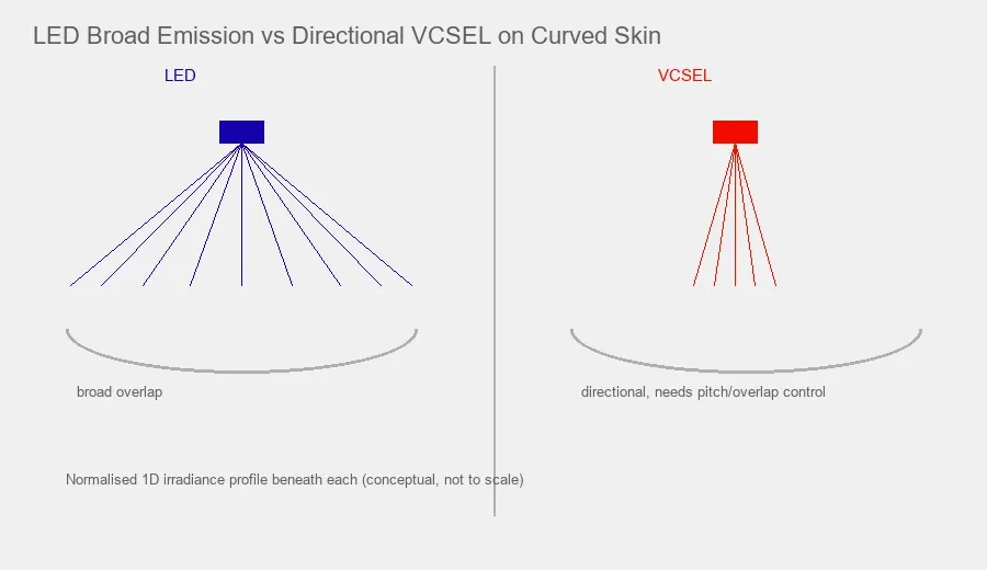
For broad emitters, increasing working distance increases overlap between neighbouring beams — improving uniformity, but reducing local irradiance and potentially increasing stray light. For a directional source the opposite appears: narrow beams close to the skin at excessive pitch produce high irradiance directly below each emitter and much lower irradiance between them.
- Narrower beam + larger pitch → visible hot spots.
- Narrower beam + smaller pitch → better overlap, but higher emitter count, electrical load, PCB area and thermal density.
- Broader beam + short working distance → stronger overlap, but more cross-illumination into the eye region.
As a starting point for broad-emitter arrays, pitch is often set so neighbouring beams reach roughly half-intensity overlap at the minimum design standoff —
approximately p ≤ 2·d·tan θ, where θ is the half-angle at half-maximum. Treat this as a seed value for simulation, not a specification.
Developing the layout
Begin with the mechanical CAD model of the mask, not a flat PCB drawing. Place representative facial surfaces at minimum and maximum expected standoff, then iterate: select a candidate wavelength and source family; obtain the actual angular intensity distribution from the supplier as data rather than a single beam-angle number; build a first emitter grid from the target area and required dies per cm²; simulate overlapping irradiance including both angular terms; adjust pitch, local density and drive current around the nose, cheek transition and jaw; then prototype and scan irradiance on a three-dimensional fixture, repeating after thermal steady state.
If the mechanical design changes late in development, the optical layout must be revalidated rather than assumed equivalent.
Define uniformity with a measurement method
There is no universal uniformity number every facial mask must meet. Define your own criterion — minimum ÷ mean irradiance, max-to-min ratio, coefficient of variation across a grid, or percentage of treatment area inside a specified window — and keep the measurement method fixed.
The metric matters less than consistency. Every test report should state instrument and calibration date, sensor aperture and cosine correction, detector wavelength response, measurement distance and fixture geometry, grid spacing, sensor orientation relative to the local surface normal, operating mode and drive current, ambient temperature, time after power-on, and whether all channels are active simultaneously.
Without those conditions, “30 mW/cm² average irradiance” is hard to compare between prototypes and impossible to compare between vendors.
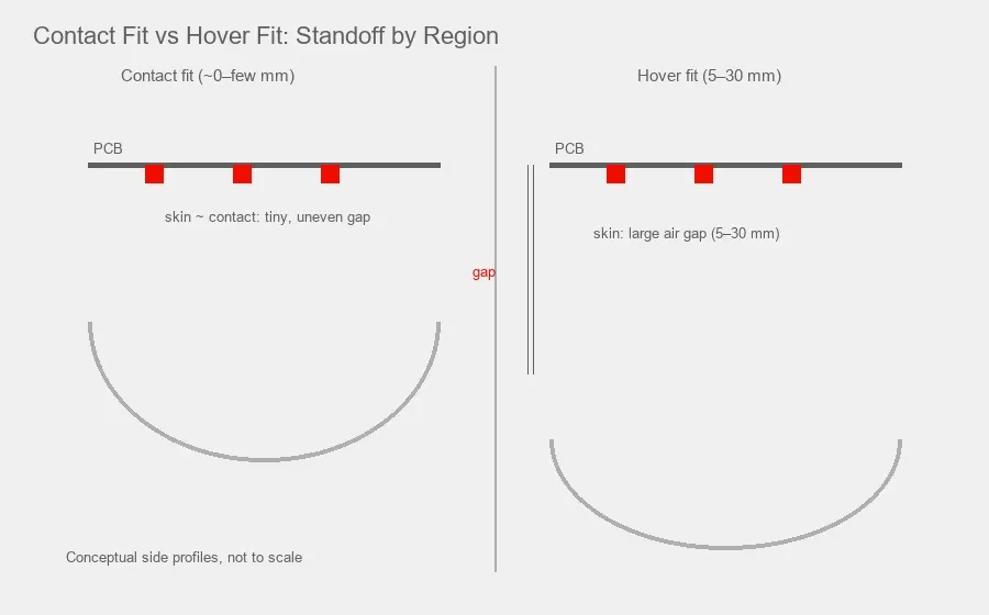
Contact fit or hover fit
This is one of the earliest decisions in a mask programme, and it changes almost every optical parameter downstream.
| Flexible / contact fit | Rigid / hover fit |
|---|---|---|
Illustrative standoff | ~0 to a few mm | 5–30mm depending on shell |
Irradiance at skin | Close to the emitter-plane value | Substantially lower |
Uniformity risk | Hot spots directly over emitters; needs fine pitch or diffusion | Better natural overlap; needs higher power per emitter |
User-to-user variation | Higher — conformity, local standoff and pressure vary with face shape and fit | Mechanical geometry is more controlled, although facial anatomy still introduces variation |
Thermal risk | Higher — silicone traps heat against skin | Lower — air gap between emitters and skin |
Eye-region control | Harder; emitters sit close to the orbit | Easier; more room for shielding and exclusion zones |
Neither is automatically better. What matters is that the choice is made before emitter selection, because a contact-fit mask usually wants many low-power, broad-emission dies at fine pitch, while a hover-fit mask usually wants fewer, higher-power emitters with controlled beam distribution.
LED and VCSEL solve different design problems
LED and VCSEL are not a quality ranking. They have different optical and integration characteristics.
Design question | LED | VCSEL |
|---|---|---|
Large-area coverage | Often straightforward with broad emission | Requires pitch and beam overlap to be engineered carefully |
Component cost | Usually lower | Usually higher |
Wavelength definition | Suitable for many PBM products; spectral width typically tens of nm | Cavity-based emission supports tighter wavelength targeting and narrower spectral width |
Wavelength shift with temperature | Device dependent — check peak-wavelength shift at the intended current and junction temperature | Device dependent; cavity wavelength is often specified with a relatively predictable temperature coefficient |
Beam directionality | Typically broad | Typically more directional |
Surface-mount integration | Widely available | Available in compact SMD and custom multi-wavelength formats |
Safety assessment route | Normally assessed as an LED photobiological source under IEC 62471 | |
Best use case | Broad, economical illumination | Designs that value directional control, wavelength behaviour or compact laser integration |
For many red light masks, LED is the simplest choice. VCSEL becomes more interesting when the architecture benefits from controlled beam direction, specific wavelength behaviour, small surface-mount packages or multi-channel integration — for example, when a narrow spectral width is needed to keep a channel inside a declared wavelength window across the full operating temperature range.
A hybrid design is also possible. A package can combine LED red light with a near-infrared VCSEL
channel, or a platform can mix LED and VCSEL populations on the same board. 1ONELASER lists a 415nm LED / 633nm LED / 850nm VCSEL 5050 SMD for multi-channel optical source development. The existence of this type of component is useful from an integration perspective, but the component itself does not establish the efficacy or safety of a finished mask.
Heat must be designed at the system level
Photobiomodulation is generally intended to operate without tissue heating as the primary mechanism, but the device still generates heat — in the emitters, drivers, traces, battery and power electronics. A flexible silicone mask compounds this, because its materials are selected for comfort rather than thermal conductivity.
Three consequences. User comfort limits the temperature tolerable on a device held against the face for 10–20 minutes. Emitter output and peak wavelength change with junction temperature, so a channel inside its declared window at power-on can drift outside it by end of session. Thermal gradients across the board create optical differences between regions even when components matched well at room temperature.
Run the thermal test for the full treatment duration at the highest intended ambient and operating mode — all channels on, longest programme, warmest room — and measure emitter and PCB hot spots, skin-facing surface temperature at several locations, battery and driver temperature, per-channel optical output at start and end of session, and peak wavelength shift where tolerance matters.
Do not rely on a component junction-temperature rating alone. A device can stay well below semiconductor limits and still become uncomfortable or optically unstable.
Eye region and photobiological safety
This is the part of a mask design most often deferred until it is expensive to change.
Two standards families are usually relevant, and which applies depends on the source type. IEC/EN 62471 covers photobiological safety of lamps and lamp systems including LEDs, over roughly 200nm – 3000nm, assigning a risk group from Exempt (RG0) through RG3 based on how quickly a realistic exposure would reach a hazard limit; lasers are explicitly outside its scope. IEC 60825-1 covers laser products, and a VCSEL-based design will generally need classification of the finished product rather than the die alone.
Two practical points catch facial-device teams:
Near-infrared is invisible, so the aversion response does not protect the user. Risk-group logic for visible sources often relies on blink and look-away behaviour. An 830nm or 850nm channel provides no such cue, so NIR eye exposure needs explicit geometric or mechanical control rather than a behavioural assumption.
The risk group of the component is not the risk group of the product. A diffuser, an exclusion zone, shell geometry or a supplied eye shield all change the assessment, and an array can behave differently from a single emitter. The assessment must be done on the finished mask in its intended use position.
Design options for the eye region, roughly in order of robustness: mechanical exclusion (no emitters in the orbital zone), opaque shielding integrated into the shell, geometric tilting of nearby emitters away from the eye, and supplied eye protection. The first two are generally preferred because they do not depend on user compliance.
The applicable safety route should ultimately be confirmed for the finished product, its intended use and each target market, because medical or cosmetic devices may also fall under product-specific standards and regulatory requirements beyond these two horizontal standards.
Component consistency is one layer, not the whole plan
Wavelength binning, optical power binning and forward-voltage consistency make production validation easier by reducing the variation the finished design must absorb. They should not be described as the single factor determining treatment performance.
A tightly binned emitter still performs poorly if the layout leaves weak coverage at the jaw, if the mask sits farther from one user than another, if the current driver is unstable, or if thermal drift changes output during the session. Treat consistency as one layer:
Component binning + current control + mechanical repeatability + optical layout + thermal control + finished-device measurement
Validate the finished mask rather than extrapolating from the datasheet
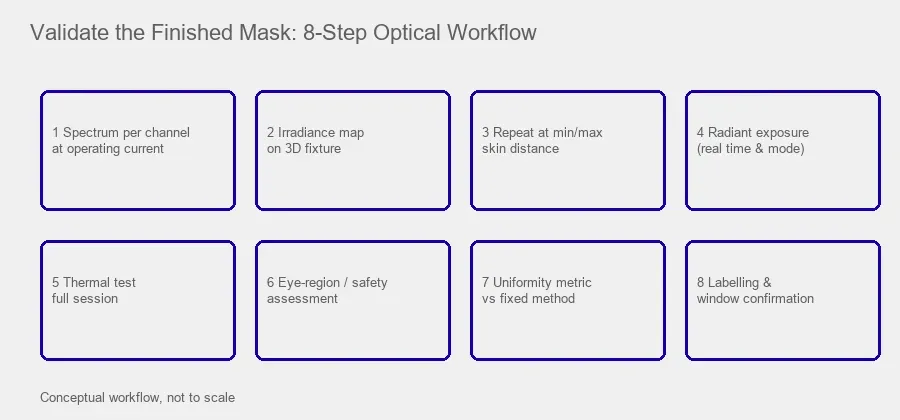
- Measure the spectrum of each wavelength channel at the actual operating current.
- Map irradiance across the treatment surface on a three-dimensional fixture.
- Repeat the map at representative minimum and maximum skin distances.
- Measure radiant exposure using the real treatment time and mode.
- Repeat optical measurements after thermal stabilisation.
- Check unit-to-unit variation across multiple builds and component lots.
- Evaluate eye exposure and applicable photobiological or laser safety requirements on the finished device.
- Confirm labelling, intended use and regulatory path match the finished device rather than the component.
FDA 510(k) summaries for LED masks report wavelength, irradiance, treatment time and energy dose as separate technical characteristics. That is a useful reminder that a mask is specified as an optical system, not by wavelength alone.
A note on regulatory framing
Decide the intended claim early, because it changes what evidence and testing the project needs. In the United States, wrinkle-reduction, acne or other medical claims generally bring the device within medical device requirements, commonly via the 510(k) route, while a general wellness positioning follows a different path. FDA has issued a draft guidance on premarket notification for photobiomodulation devices — draft guidance is non-binding and reflects current thinking, so treat it as a planning input and confirm its status before relying on it. Note also that “FDA cleared” and “FDA registered” are not the same thing; establishment registration is not a review of the device.
None of this is legal advice. Confirm current requirements with your regulatory consultant for
your specific claims and markets.
A practical selection checklist
Before requesting samples from a light source supplier, provide:
Requirement | What to send |
|---|---|
Intended application | Facial mask, neck mask, eye-area device or another platform |
Fit architecture | Contact/flexible or hover/rigid, with shell concept |
Wavelength | Nominal wavelength and acceptable tolerance, per channel |
Treatment area | Approximate illuminated area in cm² |
Target irradiance | At the actual skin distance, per channel and combined |
Treatment time | Continuous or programmed sequence |
Working distance | Minimum, typical and maximum by facial region |
Emitter pitch / density | Current design target, and dies per cm² if known |
Beam requirement | Broad distribution, defined divergence, or secondary optics |
Source format | LED, VCSEL, SMD, bare die or mixed package |
Operating mode | CW, pulsed or sequential channels, with duty cycle |
Drive | Current per emitter, per string, and driver topology |
Thermal constraints | Maximum board and skin-facing surface temperature |
Safety route | Intended IEC 62471 / IEC 60825-1 strategy |
Production requirement | Sample quantity, binning need, expected annual volume |
This lets a supplier recommend a component against the device architecture rather than sending the highest-power part at the requested wavelength.
What the supplier should return
A serious response is more than a part number. Ask for angular intensity raw data (not just a single beam-angle figure), L-I-V curves at the operating temperature, spectral shift versus current and temperature, the binning definition, and reliability data. These turn the exchange into a real engineering handover rather than a catalogue quote.
Final engineering rule
For a red light face mask, source selection and source arrangement are the same design problem.
Wavelength defines the optical band. Irradiance and exposure time define the delivery conditions. Pitch, beam distribution and working distance determine uniformity. The mechanical structure sets the real skin distance. Thermal design determines whether those values stay stable during use.
LEDs remain the practical default for many masks because broad-area illumination is straightforward and economical. VCSELs are useful when their wavelength behaviour, directional output or integration format solves a real system requirement.
The strongest design is not the one with the most emitters or the highest component power. It is the one that produces a measured, repeatable optical field across the face under the same mechanical and thermal conditions in which the user will actually wear the product.
Frequently Asked Questions
What wavelengths are commonly used in a red light face mask?
Visible red around 630nm to 660nm is common, and many designs add near-infrared around 830nm to 850nm. Cleared devices declare either narrow tolerances such as 633 ± 10nm or broader bands such as 620nm – 690nm. The final choice should follow intended use, supporting evidence and finished-device validation rather than a universal rule.
How do you calculate the light dose from a face mask?
For constant output, radiant exposure in J/cm² equals irradiance in mW/cm² multiplied by exposure time in seconds and divided by 1000. For example, 30 mW/cm² for 600 seconds is 18 J/cm². This does not mean every irradiance-and-time combination with the same total J/cm² is biologically equivalent.
How many LEDs should a red light face mask have?
There is no correct number, and published counts are not comparable because brands count packages, dies or apparent emission points differently — published commercial examples range from roughly 130 to 650, although counting methods differ. A more useful specification is emitter density in dies per cm² of treatment area, stated alongside beam angle, pitch and working distance.
Is 30 mW/cm² enough for a red light mask?
Declared red-channel irradiance on cleared and commercially marketed facial devices spans at least 26 to 73 mW/cm², so there is no consensus threshold to compare against. Whether a figure is appropriate depends on session time, target radiant exposure, how it was measured, and the validation the manufacturer plans to rely on.
Is VCSEL better than LED for a red light mask?
Not automatically. LEDs are widely used because they are economical, cover large areas easily and follow a straightforward photobiological safety route. VCSELs help where directional output, compact integration, narrower spectral width or tighter wavelength targeting is valuable — at the cost of higher component price and a laser-classification route for the finished product.
How should light sources be spaced in a red light mask?
Spacing follows from angular intensity distribution, working distance, facial curvature and the target irradiance map. A common starting point for broad emitters is to set pitch so neighbouring beams reach roughly half-intensity overlap at the minimum design standoff, then refine by simulation and measurement.
Does the mask need to touch the skin?
Both architectures are used commercially. Contact designs deliver irradiance close to the emitter-plane value but carry higher hot-spot and thermal risk. Hover designs give more natural beam overlap and easier eye-region control, but lose irradiance with distance and need higher per-emitter power. Decide before emitter selection, because it changes the optimum source.
Does higher irradiance make a red light mask more effective?
Not necessarily. Photobiomodulation research reports a biphasic response, and irradiance can matter independently of total radiant exposure. Higher irradiance should be validated as part of the complete optical protocol rather than treated as an automatic improvement.
What safety standards apply to a red light face mask?
LED-based masks are normally assessed under IEC/EN 62471, which assigns risk groups from Exempt to RG3; laser-based sources such as VCSELs generally fall under IEC 60825-1 instead. Near-infrared channels need particular attention because the light is invisible and the aversion response does not apply. The assessment must be done on the finished product in its intended use position, and product-specific standards may also apply depending on intended use and market.