
Oct 6, 2026Technical Insights
How to Select a Red Light Source for a Hair Growth Device
Select a red light source for a hair-growth device by matching evidence, wavelength, delivered irradiance, emitter layout, packaging, and production consistency.
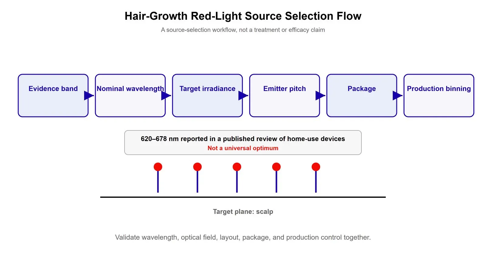
A hair-growth device should not select a red light source by asking which wavelength is “best” in isolation. A published systematic review of FDA-cleared home-use LLLT devices reports red sources across 620nm – 678nm, while the optimum wavelength, coherence, and dosimetry are still not settled. Start with the evidence base for the intended product, then qualify wavelength tolerance, delivered irradiance, emitter layout, package, thermal behavior, and production consistency.
For an OEM team, that order is more useful than choosing 650, 660, or 680nm first and solving the rest later. The wavelength puts the design in a relevant part of the red spectrum. The finished device still has to deliver a controlled optical field to the scalp, fit the mechanical architecture, remain comfortable in use, and reproduce the same output across production lots.
The published range is a starting point, not a single winning wavelength
A 2021 systematic review of FDA-cleared home-use LLLT devices reported red light and laser sources across 620nm – 678nm in the included device designs. Individual trials have also used specific red wavelengths, including a 655nm randomized controlled trial.
That does not establish a universal ranking where 650nm is better than 660nm or 680nm. An earlier review of low-level light therapy for hair loss concluded that the optimum wavelength, coherence, and dosimetric parameters remained to be determined. For an engineering team, the honest conclusion is that wavelength selection should follow the evidence and validation strategy for the specific device rather than a generic “best nm” claim.
A broader guide on the best wavelength for red light therapy devices explains how the wider red band should be treated as a design input rather than a score.
Choose the nominal wavelength from evidence and product strategy
The first decision is not which supplier has a part in stock. It is which wavelength your product program is prepared to validate.
For a new hair-growth cap, helmet, comb, or band, list the wavelengths used in the clinical or technical evidence relevant to the intended use, then decide whether the new design is meant to stay close to an established architecture or intentionally evaluate a different red wavelength. That gives the engineering team a defensible reason for the nominal wavelength before component selection begins.
Published devices in the review span 620nm – 678nm, including designs around 650, 655, and 660nm. For a specific product program, 680nm is an adjacent wavelength option, but it does not constitute equivalent evidence without device-specific validation. None of these wavelengths are interchangeable simply because they are all red. The source spectrum, peak tolerance, operating temperature, output, geometry, and device regimen must still be qualified together.
Do not confuse nominal wavelength with production wavelength control
A part labeled 650nm does not tell you how tightly every device in production will sit around that nominal value. The datasheet should state the applicable wavelength tolerance and test conditions, and the supplier should be able to explain how parts are screened or binned if the project needs a narrower production window.
This distinction becomes important after prototype approval. A prototype may use a small group of hand-selected parts, while production draws from a much larger population. If peak wavelength and optical power are allowed to spread too widely, the finished-device population can spread with them.
That is why production consistency should be treated as part of source selection rather than a problem left for final inspection. For a volume program, ask for the wavelength bin, optical-power bin, test temperature, test current, and lot-level data that will be applied to the parts you actually buy.
Set power from the scalp target backward
Per-emitter milliwatts are not the final design target. The useful engineering quantity is the optical field delivered at the scalp under the real emitter spacing, working distance, duty cycle, and mechanical geometry.
A first-order relationship is:
average irradiance over a defined target area = optical power incident on that area ÷ area
and, for a fixed irradiance during an exposure period:
radiant exposure = irradiance × time
These equations are simple, but they give an average over a defined area; spatial uniformity still requires mapping the irradiance across the target plane. The remaining difficulty is determining how much of the emitter output actually reaches the scalp. Hair, source angle, emitter-to-scalp distance, package height, lens or window losses, and overlap between neighboring emitters can all change the delivered field.
This is why “5 mW or 7 mW?” is not enough to specify a hair-growth device. Measure irradiance and uniformity at the target plane with the actual mechanical stack.
Emitter count and spacing can matter more than a higher per-emitter number
A cap with many closely spaced lower-power sources can create a different field from a cap with fewer higher-power sources, even if the summed emitter power looks similar on paper. The pattern depends on beam divergence, emitter pitch, working distance, and how much neighboring beams overlap at the scalp.
For a cap or helmet, map the irradiance across representative scalp positions rather than validating only the point directly under one emitter. For a comb or localized device, include the contact geometry and the way the user changes the source-to-scalp distance during use.
This is also where a source with more directional emission can help or hurt. Directionality can keep more light in the intended region, but a narrow or annular beam can produce peaks or gaps if the layout is wrong. Uniformity is a system result, not a property you can infer from the word “laser.”
Package selection is part of the optical design
A thin wearable product has different packaging constraints from a laboratory prototype. SMD packages simplify PCB or FPC assembly and reduce the mechanical height compared with traditional TO-can laser packages. Bare die supports denser, project-specific optical layouts, but the device maker or packaging partner must own die attach, wire bonding, protection, and the thermal path.
The current 650nm 5mW VCSEL SMD Series is specified at 5.5 mW typical at 10 mA under CW test conditions and is offered in 1615, 2835, 3030, 3535, and 5050 package options. Those figures describe this series, not red VCSELs as a category, and the final choice still depends on emitter pitch, board architecture, and thermal limits.
If the project has not settled the integration route, a separate guide compares SMD or bare die from the standpoint of pitch, assembly capability, and thermal responsibility.
A real product line can change wavelength between generations
The published range above is one kind of evidence. Supplier and OEM program history is a different kind, and it should be read as engineering experience rather than clinical support for any wavelength.
One U.S. hair-growth brand supported by our team began with a 680nm 2835 configuration. Later product work moved toward 660nm, with 650nm planned for subsequent development. The useful lesson is not that the later wavelength is universally better. It is that the wavelength decision can change as the product platform, evidence strategy, sourcing requirements, and mechanical architecture change.
That is a more realistic way to treat red-light development. A team may start with one wavelength because it fits the first product and later standardize on another because the next generation has different constraints. The supplier therefore needs to support the program at the level of wavelength, screening, package, and production data, not simply sell one nominal part number.
All customer references in this example are anonymized. Finished-device performance, medical claims, safety, and regulatory clearance remain the responsibility of the device manufacturer. In the United States, devices that fall under FDA product code OAP (“Laser, Comb, Hair”) are Class II devices with a 510(k) submission pathway. The applicable classification and regulatory requirements depend on the finished device's intended use and design.
Use this source-selection sequence before requesting samples
1. Define the evidence band
List the wavelengths and operating conditions used in the evidence relevant to the intended product. Do not turn one published device into a universal standard.
2. Set the nominal wavelength and allowable tolerance
Specify the center wavelength you want to evaluate, then ask how the supplier controls peak-wavelength spread at the stated temperature and current.
3. Translate the device target into an optical requirement
Define the useful illuminated area, working distance, emitter count, and target-plane irradiance you need to validate. Do not specify the project only as “5 mW per emitter.”
4. Choose emitter layout and package together
Set emitter pitch from the optical field first, then check whether the required SMD package fits. Move to bare die only when the pitch or mechanical architecture genuinely requires it and the assembly process can support it.
5. Define the thermal and drive conditions
State CW, pulsed, or QCW operation where applicable, drive current, ambient condition, duty cycle, and available heat path. A power rating without operating conditions is incomplete.
6. Set the production-control requirement
Ask what wavelength bin, power bin, lot traceability, and test data will be supplied for pilot and production lots. Prototype behavior is not enough evidence for volume consistency.
7. Validate a small batch in the actual device
Measure the optical field, temperature, electrical load, and mechanical fit in the finished optical stack before committing the source architecture to volume production.
About 1ONEVCSEL
1ONEVCSEL is the VCSEL product line of 1ONELASER. The red portfolio covers 650, 660, 665, 670, 678, and 680nm families in selected bare-die, SMD, and COB configurations, with screening and packaging support for OEM and R&D projects. Exact output, drive mode, beam profile, and package availability vary by wavelength and model. The device maker remains responsible for the finished product, including its claims, safety, and regulatory clearance.
For a hair-growth device evaluation, the most useful starting information is the target wavelength, acceptable tolerance, required optical output, emitter count or pitch, working distance, package preference, drive mode, and pilot quantity. Engineering samples and small evaluation batches are available; validate a small batch in the actual cap, helmet, comb, or scalp-light architecture with per-lot test data before freezing the production specification.
Frequently asked questions
Is 650nm better than 660nm for a hair-growth device?
There is no universal evidence-based ranking that makes 650nm categorically better than 660nm. Published hair PBM and LLLT studies use multiple red wavelengths, and reviews still note uncertainty around the optimum wavelength and dosimetry. Choose the wavelength from the evidence and validation plan for the specific device.
Why is 655nm common in published hair-growth studies?
655nm appears in randomized hair-growth studies, including devices that combined 655nm laser and LED sources. Its presence in the literature is useful when reviewing prior device designs, but it does not mean every new product must use 655nm or that adjacent wavelengths are equivalent without validation.
How much optical power should each emitter have?
There is no single per-emitter number that fits every hair-growth device. Work backward from the optical field required at the scalp, then choose emitter power, count, pitch, working distance, and beam geometry that can produce and reproduce that field. Confirm the result by measurement in the actual device.
Can an LED be used instead of a VCSEL in a hair-growth device?
An LED can be a valid source if the product architecture, evidence base, optical field, and validation plan support it. A VCSEL is worth evaluating when narrower spectral output, directional emission, a project-specific wavelength bin, or a particular laser-based architecture solves a real device requirement. Source category alone does not establish finished-device performance. A companion guide works through how to compare a VCSEL and an LED at the system level rather than by category.
Should a hair-growth cap use SMD or bare-die VCSELs?
Use the optical layout to decide. If an SMD package can meet the required emitter pitch and mechanical height, it simplifies assembly. Bare die becomes useful when the design needs denser placement or custom packaging and the manufacturing process can handle die attach, wire bonding, protection, and thermal control.
What should an OEM send a VCSEL supplier before sample selection?
Send the target wavelength and tolerance, optical output requirement, working distance, target area, emitter count or pitch, package preference, drive mode, thermal conditions, and pilot quantity. If the current design already has a problem, include that limitation as well so the sample is selected against the device requirement rather than the catalog alone.