
905nm
905nm 70W Multi-Junction VCSEL Bare Die
905nm 70W multi-junction VCSEL bare die with 70W typical pulsed output at 15A, 5ns operation and a 52-emitter array for rangefinding and OEM modules.
Specifications
- Product Type
- Multi-Junction VCSEL Bare Die
- Wavelength
- 905nm typ.; 895nm – 915nm
- Optical Output Power
- 60W min. / 70W typ.
- Emitter Configuration
- 52 Emitter Array
- Operating Mode
- Pulse; 5ns pulse width, 0.1% duty cycle
- Die Size
- 370 ±10μm × 450 ±10μm
- Recommended Assembly
- Die Attach / Wire Bonding / Ceramic Submount / Custom Packaging
1. 905nm 70W Multi-Junction VCSEL Bare Die for High-Peak-Output Pulsed Source Development
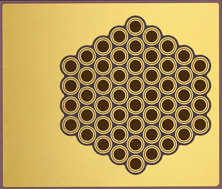
The 905nm 70W Multi-Junction VCSEL Bare Die is a 52-emitter near-infrared VCSEL array for high-peak-output nanosecond pulsed-source development, rangefinding, industrial distance measurement, semiconductor packaging and custom optical-module integration.
At a forward current of 15A, a temperature of 25 °C, a pulse width of 5ns and a 0.1% duty cycle, the device provides 60W minimum and 70W typical optical output power.
The device provides a typical peak wavelength of 905nm within a specified wavelength range of 895nm – 915nm. Its 52-emitter array and 370 × 450μm-class die support custom low-inductance packages and transmitter architectures that require substantially higher peak optical output than the 1W, 4W or 7W options.
The product is supplied as an unpackaged semiconductor bare die. It requires conductive die attachment, wire bonding, package protection, low-inductance electrical design, thermal-path planning and optical integration before use in a finished product or optical module.
Development directions include:
- High-peak-output rangefinding sources
- Industrial distance-measurement systems
- Object and presence detection
- Nanosecond pulse-driver development
- Ceramic-submount and chip-on-board integration
- Low-inductance custom VCSEL packaging
- Lens, diffuser and collimation evaluation
- High-power near-infrared optical modules
- Alternative-source and component benchmarking
Lead Time: In-stock products are dispatched within 3 business days; custom-packaged products have a lead time of 15–20 days.
MOQ: The minimum order quantity is 1 reel; selected special models support small-batch orders.
2. Optical and Electrical Characteristics
The verified product-level characteristics of the 905nm 70W Multi-Junction VCSEL Bare Die are shown below.
Parameter | Minimum | Typical | Maximum | Test Condition |
|---|---|---|---|---|
Peak Wavelength | 895nm | 905nm | 915nm | — |
Optical Output Power | 60W | 70W | — | IF = 15A, 25 °C |
Beam Divergence, 1/e² | — | 18° | — | IF = 15A |
Number of Emitters | — | 52 | — | — |
Pulse Width | — | 5ns | — | — |
Duty Cycle | — | 0.1% | — | — |
The 60W minimum and 70W typical optical-output values apply only under the stated nanosecond pulse conditions. This product must not be interpreted as a continuous-wave or long-pulse 70W source.
Performance in the completed package depends on the pulse shape, driver rise and fall time, bond-wire configuration, package and PCB inductance, current distribution, transient voltage, optical alignment and device temperature.
For projects that need lower drive current or a smaller emitting structure, review the 905nm Multi-Junction VCSEL Bare Die Series and compare the 1W, 4W and 7W options under their specified test conditions.
3. Bare Die Structure and Packaging Integration
The 905nm 70W device uses a 52-emitter array in a die measuring 370 ±10μm × 450 ±10μm, with a specified die thickness of 100 ±10μm.
Verified structural values include:
Mechanical Parameter | 70W Version |
|---|---|
Die Size | 370 ±10μm × 450 ±10μm |
Die Thickness | 100 ±10μm |
Number of Emitters | 52 |
Emitting Aperture | 20 ±1μm per emitter |
Anode Pad | 330μm × 110μm |
Backside Cathode | Full die area |
Package design should consider:
- Die orientation and electrode structure
- Conductive die-attach material and bond-line control
- Bond-wire quantity, length and current capacity
- Symmetrical current distribution across the emitter array
- Package and PCB inductance
- Ground-return structure and transient-voltage control
- Optical-axis alignment and package-window geometry
- Mechanical protection and ESD control
- Device temperature under the intended pulse condition
The 15A nanosecond pulse condition makes electrical parasitics, bond-wire current capacity and current distribution especially important. Package qualification must be performed with the intended driver, submount, PCB and optical assembly.
For direct PCB placement and reflow assembly, compare the completed 905nm 70W 3535 Multi-Junction VCSEL SMD. The SMD product and bare die are different integration forms and should not be treated as mechanically interchangeable.
Related Articles
4. Application Development
Rangefinding and Distance-Sensing Development
The 905nm wavelength and 5ns pulse condition can support component-level development of synchronized high-peak-output sources for rangefinding, industrial distance measurement, object detection and custom pulsed optical transmitters.
Product selection should consider working distance, receiver sensitivity, detector timing, target reflectivity, optical transmission loss, transmitter and receiver fields of view, pulse repetition rate, driver capability and the complete optical architecture.
The VCSEL bare die is one component of the complete transmitter. Final detection distance, ranging accuracy and system performance depend on the driver, package, optics, receiver, timing electronics, signal processing, target conditions and operating environment.
Packaging and Optical-Module Development
The unpackaged die can support ceramic-submount assembly, low-inductance chip-on-board integration, lens- or diffuser-integrated packages and customer-specific high-power near-infrared optical modules.
Final optical output and field distribution depend on die placement, package-window geometry, lens focal length, lens-to-die spacing, diffuser characteristics, mechanical tolerance and optical alignment.
These application descriptions represent component-level development possibilities. They do not establish finished-device performance, laser-safety classification, detection range or regulatory approval.
5. Evaluation Kit and Documentation Support
Evaluation samples are available for nanosecond pulse-driver development, conductive die-attach trials, wire-bonding verification, package-parasitic analysis, optical alignment and initial module integration. An Evaluation Kit with 10 pcs / KIT is available for project-specific verification, driver testing, thermal review, optical alignment and initial module integration.
Samples & Pilot Production: Evaluation kits, low-volume pilot production, and pre-production validation are supported.
The following project requirements can be reviewed:
- 70W pulsed-output selection
- 15A nanosecond pulse-driver capability
- Die, pad and emitter-array structure
- Low-inductance ceramic or chip-on-board packaging
- Wire-bond quantity and current distribution
- Optical-window, lens and diffuser integration
- Beam-profile evaluation
- Evaluation quantity and volume-supply planning
For component-level project evaluation, an Initial Product Report covering the Laser Diode Series and VCSEL Laser Diode Chip Series has been filed with the U.S. FDA CDRH. This filing supports technical documentation and product evaluation.
For applicable products, CE, EMC, EN 60825, LVD, RoHS, REACH and halogen-free certification and compliance documents are available. Documentation depends on the corresponding product model and does not represent certification of the customer's finished device.
6. Frequently Asked Questions
FAQ 1. What are the main specifications of the 905nm 70W Multi-Junction VCSEL Bare Die?
The device provides 60W minimum and 70W typical pulsed optical output at 15A and 25 °C under a 5ns pulse width and 0.1% duty cycle. It uses a 52-emitter array, has a typical peak wavelength of 905nm and measures 370 ±10μm × 450 ±10μm.
These values apply to the specified short-pulse test condition and must not be interpreted as continuous-wave ratings.
FAQ 2. What packaging factors are most important for the 905nm 70W VCSEL Bare Die?
The package should provide controlled conductive die attachment, sufficient bond-wire current capacity, symmetrical current distribution, low electrical inductance, a stable ground-return path, ESD protection and accurate optical alignment.
The intended 15A pulse driver, ceramic submount or chip-on-board structure, PCB and external optics should be evaluated together because parasitic inductance and transient behavior can materially affect the pulsed result.
FAQ 3. When should I select the 70W bare die instead of a lower-power 905nm VCSEL or the 70W 3535 SMD?
Select the 70W bare die when the project requires a customer-designed semiconductor package, direct control of the die-attach and wire-bonding structure, or a proprietary low-inductance electrical and optical assembly.
Choose the 1W, 4W or 7W bare die when lower peak output, lower current or a smaller emitting structure better matches the transmitter design. Choose the completed 70W 3535 SMD when direct PCB placement, automated SMT assembly and reflow processing are the priority.