
808nm
808nm 5mW 2835 VCSEL SMD
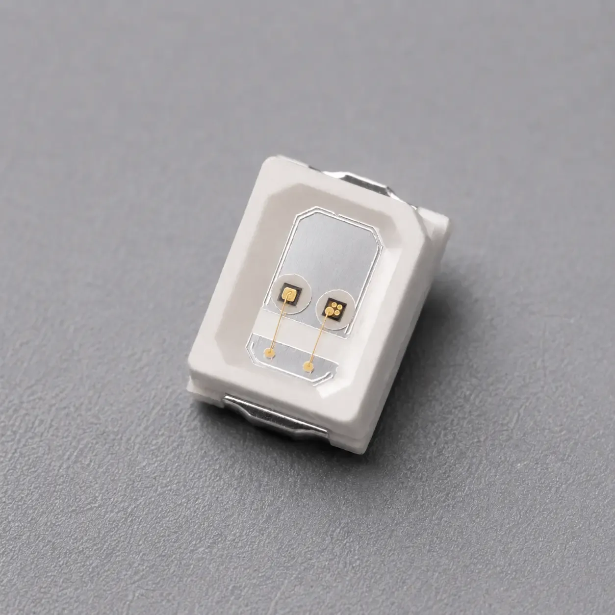
808nm 5mW VCSEL SMD in a 2835 package for compact PCB integration, pulse-driven NIR optical-source development, device selection and OEM module design.
Specifications
- Product Type
- VCSEL SMD
- Wavelength
- 808nm typ. (800nm – 816nm)
- Optical Output Power
- 5.5mW min.; 6mW typ. at IF=7mA
- Transverse Mode
- Multimode VCSEL
- Operating Mode
- Pulse
- Beam Divergence
- 21° typ. (18–24°, 1/e²)
- SMD Package Options
- 2835
1. 808nm 5mW 2835 VCSEL SMD for Low-Current PCB Optical Integration
The 808nm 5mW 2835 VCSEL SMD is a multimode near-infrared surface-mount laser source in a 3.5mm × 2.8mm package with a 0.68mm height. The 5mW class name identifies the commercial product position; the released electro-optical table specifies 5.5mW minimum and 6mW typical optical output at IF=7mA.
The released source specifies an 800nm – 816nm wavelength range with 808nm typical and a divergence angle of 18–24° with 21° typical at 1/e². The compact 2835 format provides a low-current NIR source channel for PCB-level optical measurement, sensing, alignment and OEM optical-module integration.
The handling section identifies pulse operation. It does not publish the numerical maximum pulse width or duty cycle, so the final driver release must use model-specific limits confirmed by 1ONELASER engineering rather than inferred operating limits.
Lead Time: In-stock products are dispatched within 3 business days; custom-packaged products have a lead time of 15–20 days.
MOQ: The minimum order quantity is 1 reel; selected special models support small-batch orders.
2. Optical and Electrical Performance
The released electro-optical characteristics define the current-conditioned output, voltage, efficiency, wavelength and angular performance used for component selection.
Parameter | Symbol | Min. | Typ. | Max. | Unit | Test Condition |
|---|---|---|---|---|---|---|
Threshold Current | Ith | 0.9 | 1.2 | 2 | mA | — |
Forward Voltage | VF | 1.8 | 2.0 | 2.2 | V | IF=7mA |
Differential Resistance | Rs | — | 75 | — | Ω | — |
Slope Efficiency | SE | 1.0 | 1.1 | — | W/A | — |
Optical Output Power | Lop | 5.5 | 6 | — | mW | IF=7mA |
Power Conversion Efficiency | PCE | 43 | 46 | — | % | IF=7mA |
Wavelength | λop | 800 | 808 | 816 | nm | — |
Divergence Angle (1/e²) | — | 18 | 21 | 24 | deg. | IF=7mA |
The 5.5mW minimum and 6mW typical optical-output values are tied to IF=7mA. Forward voltage, power-conversion efficiency and divergence are also specified at 7mA where the source states that condition; absolute maximum ratings are not recommended operating points.
The datasheet provides typical L-I-V curves at 20 °C, 30 °C, 50 °C and 70 °C. These curves show temperature-dependent behavior and do not replace the released Min./Typ./Max. table or the model-specific pulse limits required for the final driver.
-
-
-
-
3. 2835 Package, Polarity and PCB Integration
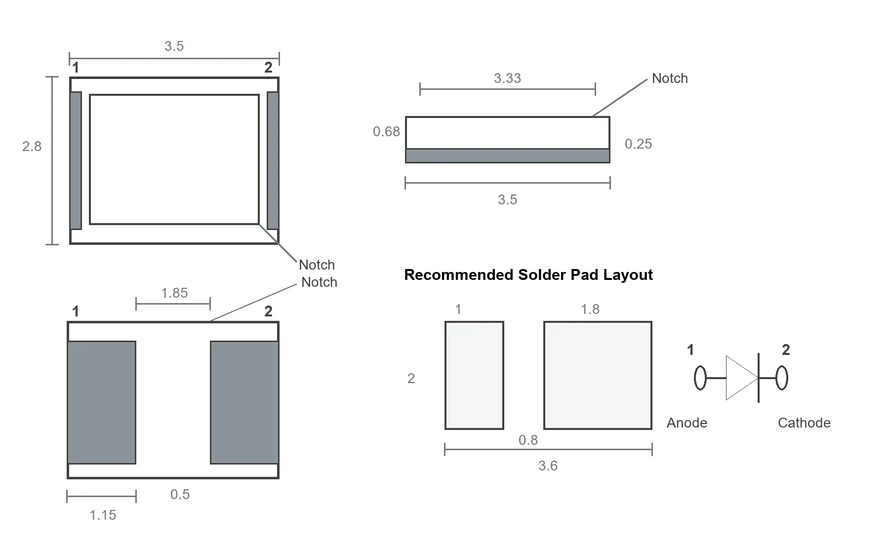
The SMD 2835 package measures 3.5mm × 2.8mm with a 0.68mm height. A package notch identifies the Pin 2 side, while the released circuit symbol assigns Pin 1 as anode and Pin 2 as cathode.
Package Item | Released Value |
|---|---|
Package Type | SMD 2835 |
Body Length | 3.5mm |
Body Width | 2.8mm |
Package Height | 0.68mm |
Polarity | Pin 1 anode / Pin 2 cathode |
Recommended Pad Span | 3.6mm overall |
Recommended Pad Gap | 0.8mm |
Production integration must verify land pattern, polarity, reflow profile, heat flow into the PCB, package coplanarity and post-reflow optical output. The package drawing is a component-level mechanical reference and does not replace the customer's PCB and assembly validation.
For family-level selection, review the 808nm VCSEL SMD Series. Projects requiring a different 5mW footprint should compare the 808nm 5mW 3030 VCSEL SMD.
For higher optical-output classes in the same 2835 package direction, compare the 808nm 10mW 2835 VCSEL SMD and the 808nm 20mW 2835 VCSEL SMD.
4. 808nm Product Selection and OEM Integration
The 808nm 5mW 2835 VCSEL SMD serves compact NIR source channels that require low drive current, a surface-mount package and a source-specified optical output at 7mA. Package choice, optical-output class and driver conditions remain separate design decisions.
Low-Current NIR Optical-Source Boards
The component supports reflective optical measurement, photoelectric sensing, optical alignment, detector testing and compact PCB NIR-transmitter assemblies. The OEM must verify the receiver, optical path, working distance, external optics, ambient-light rejection and operating waveform in the completed subsystem.
Personal-Care and Medical-Beauty Optical Subsystems
The low-current 808nm source channel supports OEM personal-care and medical-beauty optical subsystem development where the finished equipment defines emitter count, spacing, power density, thermal management, treatment geometry, safety controls and performance validation. For system-level planning, review the Medical Beauty & Personal Care Solution. The component specification does not establish clinical efficacy, treatment performance, finished-device safety approval or regulatory clearance.
Related Articles
5. Evaluation Kit and Documentation Support
A 10 pcs / KIT Evaluation Kit is available for current-driver development, PCB assembly, polarity verification, optical testing and package integration. The kit provides the commercial 808nm 5mW 2835 VCSEL SMD component configuration and supports engineering work before the customer's final system release.
Samples & Pilot Production: Evaluation kits, low-volume pilot production, and pre-production validation are supported.
For component-level project evaluation, an Initial Product Report covering the Laser Diode Series and VCSEL Laser Diode Chip Series has been filed with the U.S. FDA CDRH. This filing supports technical documentation and product evaluation.
For applicable products, CE, EMC, EN 60825, LVD, RoHS, REACH and halogen-free certification and compliance documents are available. Documentation depends on the corresponding product model and does not represent certification of the customer's finished device.
6. Frequently Asked Questions
FAQ 1. What Is the Difference Between the 808nm 5mW 2835 and 3030 VCSEL SMD Products?
Both products provide a 5mW-class 808nm surface-mount source, while their package footprints and mechanical interfaces differ. This product uses a 3.5mm × 2.8mm package with a 0.68mm height, Pin 1 anode, Pin 2 cathode and a notch at the Pin 2 side. The 3030 version must be selected from its own package drawing and released electrical data.
FAQ 2. What Optical Output Is Specified for the 808nm 5mW 2835 VCSEL SMD at 7mA?
The released table specifies 5.5mW minimum and 6mW typical optical output at IF=7mA. The 5mW wording is the commercial output class rather than a replacement for the source-specified Min./Typ. values.
FAQ 3. Which Pulse, Thermal and Assembly Conditions Must Be Confirmed Before Design Release?
The source identifies pulse operation but does not publish the numerical maximum pulse width or duty cycle. Before design release, confirm the model-specific pulse limits, current waveform, junction temperature control, heat sinking, reflow profile, polarity and ESD procedure, then validate optical output in the completed subsystem.