
Oct 24, 2026Technical Insights
Why Do Red Light Panels Feel Hot on the Skin
Why does a red light panel feel hot? An OEM guide to irradiance, distance, drive conditions, source losses, airflow, and thermal troubleshooting.
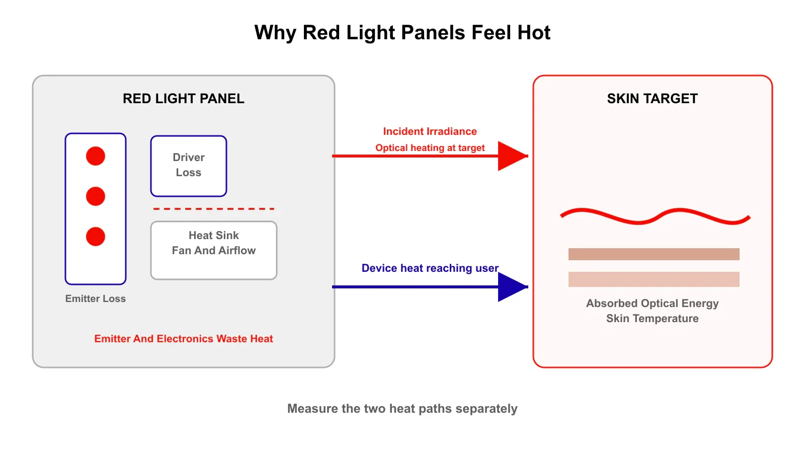
A red light panel can feel hot for two different reasons that developers should separate during troubleshooting. First, the skin absorbs part of the incident red and near-infrared optical energy and converts some of it into heat. Second, the panel itself converts part of its electrical input into waste heat, and that heat can reach the user through the front surface, through warmed air, and through thermal radiation from the enclosure. LED wattage alone cannot tell you which mechanism is dominating.
The table below maps the most common complaints to the variables worth checking first. The rest of the article explains the physics behind each row and ends with a full troubleshooting sequence and a test-record sheet.
What the user reports | Investigate first | Measurement |
|---|---|---|
Skin heats quickly but panel front stays cool | Local irradiance peak, working distance, wavelength mix, exposure time | Irradiance map plus target temperature curve |
Enclosure becomes hot before skin does | Source waste heat, driver loss, poor thermal path, blocked airflow | Board, driver, heat sink, inlet and exhaust temperatures |
Only one area feels hot | Array nonuniformity, lens angle, distance, emitter alignment | Two-dimensional irradiance map |
Heat spikes when red and NIR run together | Total optical irradiance and total electrical load | Channel-specific irradiance and input power |
Production units run hotter than the prototype | Emitter output spread, driver-current tolerance, interface assembly, fan variation | Lot data plus multi-unit thermal test |
Start by separating skin heating from panel heating
The fastest way to waste engineering time is to treat every hot-skin complaint as an LED problem, so put two temperature measurements into the test plan. One follows the user-facing optical target: measure skin-surface temperature or a representative optical and thermal phantom during exposure under a defined starting temperature, working distance, irradiance, and time. The other follows the device: measure LED or VCSEL board temperature, heat-sink temperature, front-window or lens temperature, driver temperature, outlet-air temperature, and ambient temperature.
If skin temperature rises while the panel face and air stay relatively cool, absorbed optical energy is likely carrying more of the thermal load. If the panel face, enclosure, or outgoing air becomes hot even at modest target irradiance, the internal thermal path deserves attention. In many real products, both happen at the same time.
Low-level light is intended to be non-thermal but that does not mean temperature can never rise
Photobiomodulation is normally distinguished from deliberately photothermal treatments. In its guidance on non-invasive body-contouring technologies, the FDA places low-level light procedures in the non-thermal category. That describes the intended mechanism of those specific procedures. It is not a general definition covering every PBM device, and it is not a guarantee that a given red or near-infrared panel will produce zero measurable temperature change under every operating condition.
Experimental work shows why the distinction matters. A photothermal study of higher-energy PBM measured temperature changes under controlled optical exposure and found that wavelength, irradiance, applicator geometry, and exposure conditions can materially change heating. A separate pilot study of home-use LED PBM devices reported home-use LED device thermal measurements with measurable surface and subsurface temperature rises under the tested device and operating conditions.
These studies do not provide a universal safe irradiance or a universal temperature limit for every commercial panel. They show that thermal behavior has to be measured in the actual device rather than assumed from the words low level. This is where the engineering view departs from consumer messaging: a device maker cannot rely on the common claim that red light produces no heat, because absorbed optical energy and device waste heat are both real and both measurable.
Irradiance at the skin matters more than the wattage printed on the panel
Electrical wattage is an input to the product.
Skin receives optical irradiance.
Those are not the same quantity.
For a target area, optical dose can be expressed as:
fluence in J/cm² = irradiance in W/cm² × exposure time in seconds
For example, doubling irradiance while keeping exposure time constant doubles the incident optical energy per unit area. Whether that produces twice the temperature rise is not a simple linear rule, because heat is simultaneously conducted through surrounding tissue, exchanged with the environment, and redistributed by blood perfusion.
The important engineering point is simpler. If a design increases target-plane irradiance without changing anything else, it increases the optical power available to be absorbed by the skin.
This is why a higher-power emitter does not automatically improve a panel. A per-emitter source rating should be selected together with emitter count, pitch, working distance, and target irradiance rather than by maximum per-emitter output.
Working distance changes both irradiance and uniformity
Moving the user farther from a panel often reduces the hottest part of the optical field, but do not apply the inverse-square law blindly to a large close-range panel. A large emitter array at a short working distance behaves as an extended source rather than a single point source, so different emitters overlap differently as distance changes and the peak irradiance, average irradiance, and uniformity can change at different rates. Research on LED array near-field irradiance design shows why emitter spacing and target distance have to be designed together.
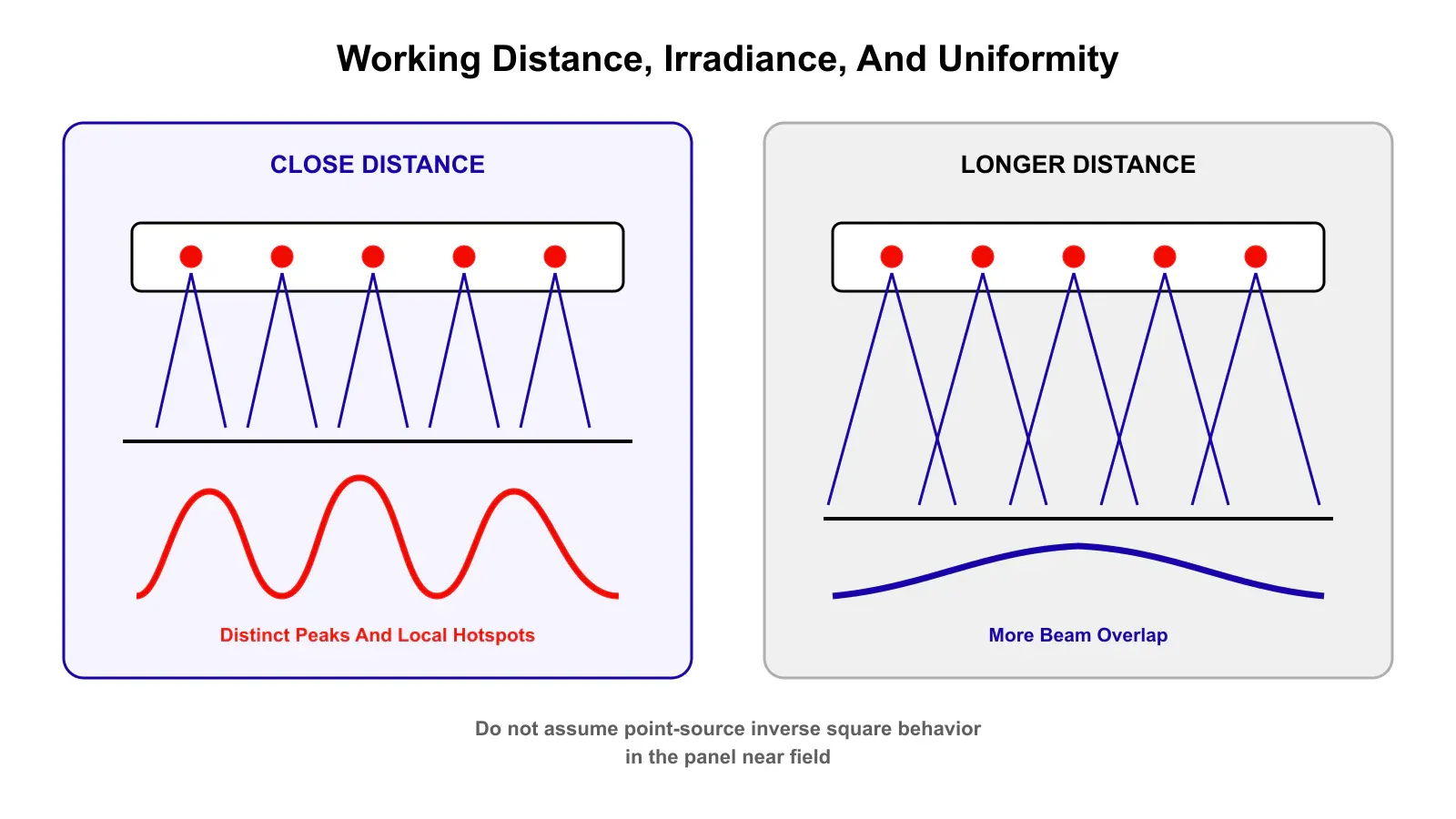
For a panel developer, the correct test is an irradiance map at every intended user distance. Publishing one center-point number measured at an unspecified distance, then using it as the thermal model for the whole treatment area, hides exactly the local peaks that drive discomfort. Record at least:
- center irradiance
- average irradiance across the useful area
- maximum local irradiance
- minimum local irradiance
- working distance
- wavelength channel or channel combination
- meter type and measurement geometry
A panel can have an acceptable average while still creating a local hotspot that drives discomfort.
Emitter pitch can create thermal hotspots even when average power looks reasonable
If neighboring beams overlap too strongly at one working distance, the target plane can develop local peaks that affect both optical uniformity and thermal behavior. A region with above-average irradiance receives more absorbed optical power and can therefore run hotter than the panel-wide average suggests. This is one reason a dense array of lower-output emitters can sometimes produce a more controllable field than fewer high-output emitters, though it is not a universal rule because beam divergence, lensing, diffuser design, and distance change the result.
The practical step is to model and measure the complete array: for each candidate layout, create a two-dimensional irradiance map at the actual skin plane, compare the peak-to-average ratio, and repeat the thermal test at the optical peak rather than only at the geometric center. For emitter-level spacing and per-emitter power selection, the 660nm red light source guide covers emitter count, pitch, and 5 mW versus 7 mW selection in detail, so this article keeps its focus on thermal diagnosis.
Electrical power that does not become useful light becomes heat somewhere
An LED or laser source does not convert all electrical input into optical output. Losses occur through non-radiative recombination, electrical resistance, optical absorption inside the package, and other mechanisms, and those losses become heat in the source and the surrounding structure. To a first order, the heat generated at the source is the electrical input it does not turn into light:
P_heat ≈ P_electrical − P_optical
This is a source-level estimate only. Driver, control-board, and power-supply losses are separate terms that have to be added into the full system heat budget, so a panel dissipates more total heat than this expression alone predicts.
Junction temperature can then be estimated from the dissipated heat and the thermal resistance between the junction and a defined reference point:
T_j ≈ T_ref + R_θJ-ref × P_heat
Here T_j is the junction temperature, T_ref is the temperature at a defined reference point, and R_θJ-ref is the thermal resistance from the junction to that reference. For an SMD device the reference may be the solder point and the datasheet may provide a junction-to-solder resistance, while COB, bare-die, and array packages may define a case, submount, or another thermal reference instead. Use the reference points the supplier actually specifies, since the value depends on how and where it is measured. This first-order relationship is most useful under steady-state or quasi-steady-state conditions. For short-pulse operation, use the supplier transient thermal impedance data where available rather than applying steady-state thermal resistance directly. A review of LED junction-temperature measurement describes the multiple heat-generation paths inside LED packages and why junction temperature depends on the complete thermal resistance path to the environment.
This is where source efficiency affects the panel. A less efficient optical source requires more electrical input to deliver a given optical output and can therefore place a larger waste-heat load into the board, the heat sink, and the enclosure. That is not license to compare technologies by an unsupported category claim such as every VCSEL running cooler than every LED, or the reverse. Compare the selected parts under the same wavelength, optical output, current, temperature, and package conditions, then compare how much electrical power the finished panel consumes to produce the target-plane irradiance you actually need.
Driver losses can heat the enclosure even when the optical output is unchanged
A driver converts the product supply power into the current waveform used by the emitters, and that conversion is not lossless. MOSFET conduction, switching, inductors, resistors, rectification, and power conversion all add heat inside the product, and a driver mounted behind the emitter board may warm the same enclosure and airflow path used to cool the sources. A thermal investigation should therefore record electrical input at the wall or DC supply alongside electrical power delivered to the emitter channels. The difference is not all driver loss, since other electronics also consume power, but it gives a power budget: if two revisions produce the same target irradiance and one draws substantially more electrical power, the extra loss has to go somewhere.
How drive mode changes thermal behavior
Pulsing is often proposed as a heat fix without defining what stays constant. If PWM reduces duty cycle while peak current stays the same, average electrical input and average optical output can fall, which can reduce average heating. If the designer then raises peak current so that average optical power and delivered dose return to the previous level, the thermal advantage may shrink or disappear, and junction temperature and transient peak-current limits still have to be respected. The useful question is not whether pulsed light is cooler but what the peak current, pulse width, repetition rate, duty cycle, average electrical power, average optical power, and delivered fluence actually are. Only with those defined can two drive modes be compared fairly.
Exposure time is a related lever. A given fluence can be delivered with higher irradiance for a shorter time or with lower irradiance for a longer time, and these are not necessarily thermally equivalent, because a longer lower-irradiance exposure lets more heat leave while the light is being delivered and can lower the peak temperature reached during the session. This is not a biological-equivalence rule: PBM response may depend on irradiance and time rather than on fluence alone, and a device clinical or performance validation cannot be replaced by thermal arithmetic. But as a thermal-design experiment, lowering irradiance and extending time is a useful variable to test when a product is exceeding its comfort target.
Wavelength changes absorption and heating but there is no simple red versus NIR rule
Users sometimes report that one wavelength channel feels warmer than another. That observation can be real, but it should not be converted into a universal statement that red is hotter or near-infrared is hotter. Skin contains wavelength-dependent absorbers including melanin, hemoglobin, and water, and scattering also changes with wavelength, so the fraction of incident power absorbed near the surface changes across the red and near-infrared range. At the same time, commercial panels rarely hold all other variables constant between channels, since red and NIR emitters may differ in electrical efficiency, optical output, beam angle, count, lens, and drive current.
The reliable test is channel by channel: measure red only, NIR only, and combined operation at matched target-plane irradiance where possible, and record the irradiance map and the skin-temperature curve for each condition. The best wavelength for red light therapy devices should still be selected from the intended optical and biological target, with temperature treated as one of the constraints the finished system has to control.
Heat-sink size is only one part of panel cooling
A large aluminum heat sink still performs poorly if the heat does not reach it efficiently. Follow the thermal path from the junction outward, since each interface adds thermal resistance:
junction → package → solder or die attach → PCB or MCPCB → thermal interface → heat sink → enclosure air → ambient
A practical panel review should check:
- board material and copper distribution
- thermal vias where appropriate
- source-to-board attachment quality
- thermal-interface material thickness and contact
- heat-sink contact area
- fin orientation
- fan flow rate and pressure capability
- inlet and exhaust restriction
- hot-air recirculation
- driver placement relative to emitter cooling
- enclosure vents and dust loading
- fan degradation over product life
A fan can move a large nominal air volume in free space and still perform badly once it sits behind a restrictive grille and a dense heat sink, so temperatures should be measured in the assembled enclosure.
Do not trust an infrared camera reading without checking emissivity
A common measurement error undermines otherwise careful thermal work. An infrared camera infers temperature from emitted radiation, and that inference depends on the surface emissivity it is told to assume. A bright aluminum heat sink, an anodized surface, a glass front window, and a plastic housing all have different emissivities, so pointing a thermal camera at bare polished aluminum with a default emissivity setting can produce a large error in the reported surface temperature. Reference material on infrared temperature measurement and emissivity notes that polished metals such as aluminum are so reflective in the infrared that accurate readings are not always possible without correction.
For readings that feed a design decision, prefer a contact sensor such as a thermocouple or RTD at the point of interest, or apply calibrated high-emissivity tape or paint to the spot being imaged and set the camera emissivity to match. Keep the measurement location consistent between revisions so comparisons stay valid. A hotspot that appears or disappears between two builds is only meaningful if it was measured the same way both times.
Poor cooling can also change optical output during the session
Thermal design is not only about user comfort. Junction temperature can shift optical output, wavelength, efficiency, and long-term component stress, so a panel may deliver one optical field when cold and another after several minutes. For a red or near-infrared product, log irradiance and spectrum after thermal equilibrium rather than validating only at switch-on.
This is also a production problem. Two panels built with different thermal-interface pressure, fan performance, emitter bins, or driver calibration can reach different operating temperatures and optical outputs even when their mechanical drawings are identical. A separate article explains why red light devices fail in production when source variation is not controlled, and thermal variation deserves the same population-level discipline.
Does changing from LED to VCSEL solve the heat problem
Teams sometimes ask whether switching the emitter from LED to VCSEL removes a hot-panel complaint. Not automatically, and it is worth being precise about why, because the honest answer is not that one technology is inherently cooler.
Both source types are governed by the same first-order balance: the heat generated at the source is the electrical input that does not become light, so the comparison comes down to electrical-to-optical efficiency at the wavelength, drive condition, and package you actually use, not the source category. What VCSELs change is often the optical geometry rather than the thermodynamics. Many VCSELs have more directional native emission than conventional broad-angle LEDs, although package optics and secondary optics can change the system-level comparison. That directionality can raise the irradiance delivered to the target plane for the same emitted power, so matching one source to another on emitter power does not guarantee matching skin irradiance. VCSEL arrays also have their own beam-overlap behavior, and a poorly spaced array can still build local hotspots at a given working distance.
Compare the two sources at the same target-plane irradiance and exposure plan, then compare wall-plug electrical power, delivered optical output, the irradiance map, and the full thermal path for each candidate. For teams evaluating this switch, red and NIR VCSEL sources can be assessed against the incumbent LED on exactly those measurements. A source change helps only when it improves one of them.
Use this troubleshooting sequence when users say the panel feels too hot
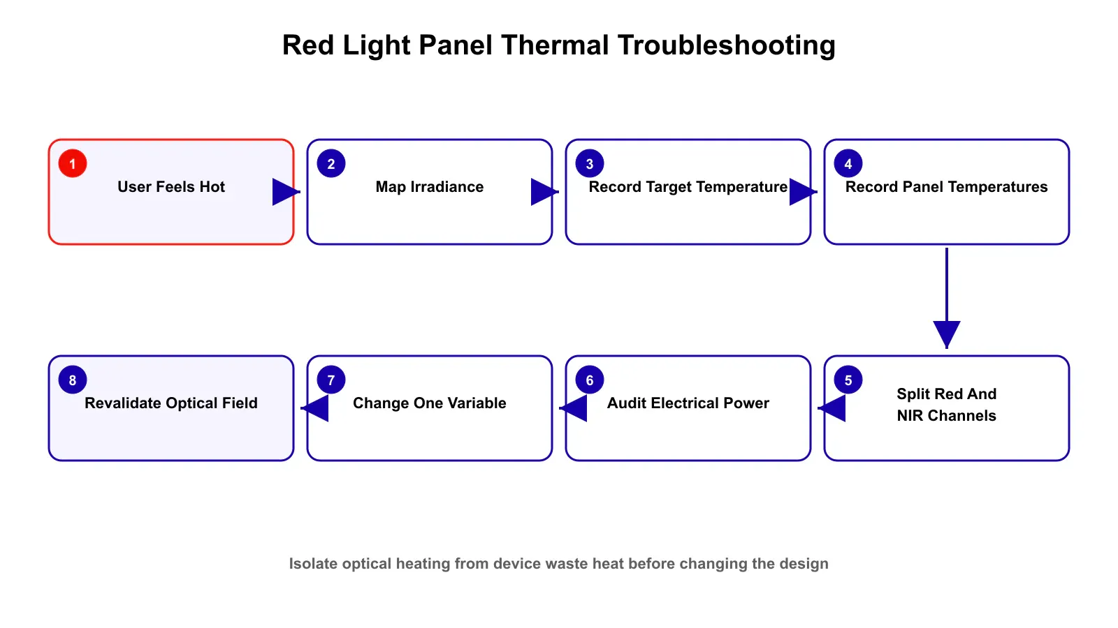
Work through the steps in order, changing only one variable at a time so each result stays interpretable:
- Reproduce the complaint under a fixed test condition. Record ambient temperature, warm-up state, distance, exposure time, selected wavelength channels, drive mode, and user-facing power setting.
- Map the optical field. Measure peak and average irradiance across the actual treatment plane and find the hottest optical location rather than assuming it is at the geometric center.
- Record a temperature curve. Measure target-surface temperature from start to finish and for several minutes after exposure, using the same initial condition for every comparison.
- Measure panel temperatures at the same time. Track emitter board, heat sink, front window, driver, inlet air, and exhaust air.
- Split the wavelength channels. Test red only, NIR only, and combined output so channel-specific optical and electrical effects can be separated.
- Audit the electrical power budget. Record input power, emitter-channel current and voltage, pulse conditions where used, and driver temperature.
- Change one variable at a time. Candidate tests include working distance, target irradiance, emitter pitch, diffusion, average drive, thermal interface, airflow, and isolating driver heat from the emitter heat sink.
- Revalidate optical dose and uniformity after every thermal change. A cooler product that no longer delivers the required optical field is not a successful redesign.
- Test the final assembly across production samples. Do not qualify one golden prototype; use multiple units and include tolerance in source output, driver current, fan performance, interface assembly, and ambient conditions.
A test-record sheet you can reuse
Capturing the same fields for every build and every complaint is what turns anecdotes into a diagnosis. The sheet below is a starting template for R&D, QA, and sourcing to fill in under a fixed test condition. It does not replace the product safety and regulatory validation.
Test condition | Record |
|---|---|
Ambient temperature | °C |
Warm-up time | min |
Working distance | cm |
Wavelength channels | Red / NIR / combined |
Peak irradiance | mW/cm² |
Average irradiance | mW/cm² |
Duty cycle | % |
Exposure time | min |
Target-surface temperature | °C over time |
Front window or user-facing panel-surface temperature | °C |
LED or VCSEL board temperature | °C |
Heat-sink temperature | °C |
Driver temperature | °C |
Inlet air temperature | °C |
Exhaust air temperature | °C |
Fan state, RPM, or measured airflow | setting or measured value |
Input electrical power | W |
The design target is controlled optical delivery with a controlled thermal path
A good red light panel is not the one with the coldest LEDs or the largest fan. It is the one that delivers the required wavelength, irradiance, uniformity, and exposure plan while keeping source junctions, electronics, enclosure surfaces, and the user-facing target within the product validated thermal range. That requires three linked designs working together: the optical design controls where the light goes, the electrical design controls how the emitters are driven and how much power is lost inside the system, and the mechanical and thermal design controls where the resulting heat goes. Changing only one of those layers usually moves the problem rather than solving it.
For teams still deciding between light-source architectures, make the VCSEL or LED comparison at the system level. For teams already evaluating VCSELs, a guide on VCSELs for LLLT and PBM devices covers wavelength, beam, and array considerations.
About 1ONEVCSEL
1ONEVCSEL is 1ONELASER's specialized product brand focused on VCSEL technology. It supplies selected visible-red and near-infrared VCSEL components in available bare-die, SMD, COB, and array configurations for OEM and R&D evaluation.
For a red-light panel or PBM-device source evaluation, useful starting information includes target wavelength, optical output per emitter or target-plane irradiance, emitter count and pitch, working distance, beam requirement, CW or pulsed operation, duty cycle, package preference, board thermal path, and prototype quantity. If you are comparing sources against a target-plane irradiance and thermal budget, send us those numbers and we recommend parts to evaluate. Start with Request Evaluation Kits.
The light source is only one part of panel heating. The finished-device manufacturer remains responsible for validating optical dose, skin-facing temperature, electrical and thermal safety, user instructions, product claims, and applicable regulatory requirements.
Frequently asked questions
Why does a red light panel feel hot even when LEDs are efficient
Because efficiency is not 100 percent and because heat can reach the user through more than one path. Part of the electrical input becomes heat inside the source and electronics, while part of the emitted optical energy is absorbed by the skin and converted to heat.
Is a hot feeling proof that irradiance is too high
No. High local irradiance can cause heating, but a hot enclosure, warm airflow, wavelength mix, long exposure, poor cooling, or a local optical hotspot can also contribute. Measure irradiance and temperature separately.
Will moving farther away reduce the heat
Often, but the effect has to be measured. A large panel at close range is an extended source, so irradiance does not necessarily follow a simple point-source inverse-square rule. Increasing distance can also change uniformity as beams overlap.
Does pulsing reduce heat
Only if it changes the relevant average power or allows enough thermal relaxation to change peak temperature. PWM is not automatically cooler when average optical output and delivered fluence are held constant.
Is near-infrared always hotter than red light
No. Tissue absorption changes with wavelength, but commercial red and NIR channels also differ in emitter count, efficiency, optical power, beam angle, and drive conditions. Compare the channels at measured target-plane irradiance rather than by wavelength label alone.
Should I lower LED power when users report heat
Possibly, but first identify whether the dominant problem is optical irradiance, a local hotspot, source waste heat, driver loss, enclosure cooling, or a combination. Reducing emitter current without finding the cause can reduce useful optical output while leaving a poor thermal design unchanged.
What should a panel manufacturer measure before production
At minimum, measure target-plane irradiance and uniformity, optical output after warm-up, target-surface temperature over time, emitter-board temperature, heat-sink and driver temperature, input power, airflow, and performance variation across multiple production samples.